
Marine outboard motor

A propeller hanger and marine technology, applied in ship propulsion, ship parts, ship construction, etc., can solve the problems of motor and controller burnout, burnt motor and controller, motor and controller heating, etc.

Active Publication Date: 2014-10-22
CHANGZHOU GOLDEN MOTOR TECH
View PDF5 Cites 9 Cited by
  • Summary
  • Abstract
  • Description
  • Claims
  • Application Information

AI Technical Summary

Problems solved by technology

[0002] At present, if the motor and controller of the traditional propeller hanger are not cooled during operation, the motor and controller will heat up, causing the motor and controller to burn out. Usually, the motor and controller are cooled by water cooling, as described in patent 200810195977.8. The patented water-cooled motor is connected to the main shaft, and the main shaft is used to provide power to control the water flow to cool the motor and controller. However, when the ship reverses, the motor will reverse, and the water will not be sucked into the motor and controller. If it lasts for a long time Reversing the time will cause the motor and controller to burn out
[0003] At present, the control handles of most paddle machines use mechanical transmission to control the speed of the motor boat through sensors when controlling the speed, and when reversing, they also use the reversing cable control sensor to drive the motor to reverse. This structure is relatively Complicated, poor reliability, cumbersome installation and maintenance

Method used


Image

  • Marine outboard motor
  • Marine outboard motor
  • Marine outboard motor

Examples


Embodiment Construction

[0019] The present invention will be described in further detail below in conjunction with the embodiments given in the accompanying drawings.

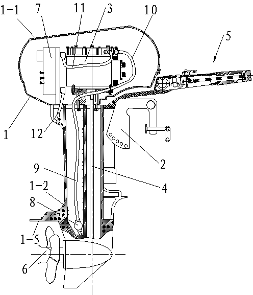
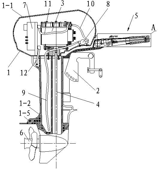
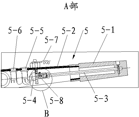
[0020] Such as Figure 1~4 As shown, a marine oar hanging machine includes a casing 1, a bracket 2, a motor 3, a main shaft 4, a control handle assembly 5, an output device 6 and a controller 7, and the motor 3 and the controller 7 are fixedly connected to the casing 1, the motor 3 is electrically connected to the controller 7, the output device 6 is connected to the casing 1, the motor 3 is connected to the output device 6 through the main shaft 4, the control handle assembly 5 is connected to the casing 1, and the control handle assembly 5 includes a rotating handle 5-1, a connecting handle 5-2, a connecting rod 5-3 and a potentiometer 5-4, one end of the connecting handle 5-2 is fixedly connected to the casing 1, and one end of the rotating handle 5-1 is sleeved on the connection The periphery of the other end of the handle 5-2, o...


PUM


Abstract

The invention provides a marine outboard motor which comprises a casing, a bracket, a motor body, a spindle, a control handle assembly, an output device, a controller and a water pump. The motor body and the controller are fixedly connected in the casing, the output device is connected and assembled with the casing, the motor body is in drive connection with the output device through the spindle, and the control handle assembly is connected and assembled with the casing. The control handle assembly comprises a rotary handle, a connecting handle, a connecting rod and a potentiometer; one end of the connecting handle is fixedly connected with the casing, one end of the rotary handle sleeves the other end of the connecting handle, one end of the connecting rod is fixedly connected with the rotary handle, and the potentiometer is connected and assembled with the connecting handle and electrically connected with the controller. The motor body is provided with a cooling passage, the controller is also provided with a cooling passage, and the cooling passage of the motor body, the cooling passage of the controller, the water pump and a connecting pipeline form a cooling system. The marine outboard motor is simple in structure, good in reliability and convenient to assemble and mount. The motor body and the controller are prevented from being burnt out even when a ship runs astern for a long time.

Description

technical field [0001] The invention relates to a marine oar hanger. Background technique [0002] At present, if the motor and controller of the traditional propeller hanger are not cooled during operation, the motor and controller will heat up, causing the motor and controller to burn out. Usually, the motor and controller are cooled by water cooling, as described in patent 200810195977.8. The patented water-cooled motor is connected to the main shaft, and the main shaft is used to provide power to control the water flow to cool the motor and controller. However, when the ship reverses, the motor will reverse, and the water will not be sucked into the motor and controller. If it lasts for a long time Reversing the time will cause the motor and controller to burn out. [0003] At present, the control handles of most paddle machines use mechanical transmission to control the speed of the motor boat through sensors when controlling the speed, and when reversing, they also us...

Claims


Application Information

Patent Timeline
IPC IPC(8): B63H20/00B63H20/28
CPCB63H20/00B63H20/28B63H20/12B63H20/007B63H21/17
Inventor 何章姚国华熊知明梁宏常
Owner CHANGZHOU GOLDEN MOTOR TECH
Learn More