
Multifunctional electronic insect zapper

An electronic insect exterminator and multi-functional technology, which is applied in the device, application, animal husbandry and other directions of catching or killing insects, can solve the problems of neglected chemical killing methods, artificial real-time swinging, and low killing efficiency. The killing methods are flexible and diverse, the killing effect is outstanding, and the killing effect is wide.

Active Publication Date: 2016-01-13
DONGGUAN LEAYARDLE PEST CONTROL TECH
View PDF7 Cites 0 Cited by
  • Summary
  • Abstract
  • Description
  • Claims
  • Application Information

AI Technical Summary

Problems solved by technology

Chemical killing used to be the most commonly used method. Although the effect is good, due to certain pollution, with the improvement of people's health and environmental awareness, chemical killing has gradually been neglected.
At present, the electronic killing devices that are relatively popular in the market are highly praised. There are mainly two ways to kill insects: active killing and passive killing. Killing efficiency is not high
Passive killing methods, such as mosquito killer lamps, use light sources and smells to lure automatic hunting, which is more convenient, but is easily affected by factors such as time, venue and environment, and its killing effect is limited
At present, the appliances using the above two killing methods on the market have single functions, and the insecticides are limited to small pests such as mosquitoes and flies, which is difficult to fully meet the needs of pest killing in the home environment.

Method used


Image

  • Multifunctional electronic insect zapper
  • Multifunctional electronic insect zapper
  • Multifunctional electronic insect zapper

Examples


Embodiment Construction

[0013] The present invention will be further described below in conjunction with accompanying drawing:

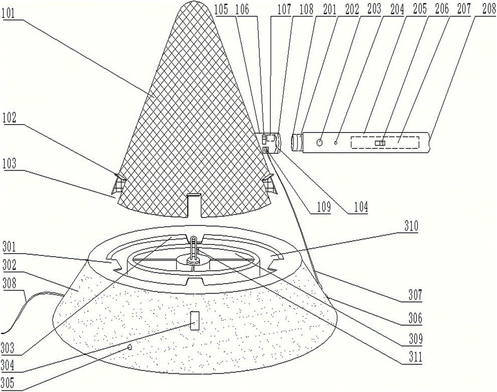
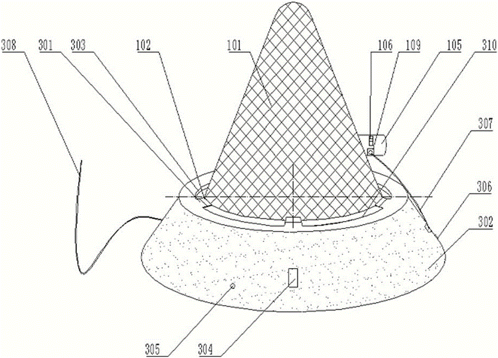
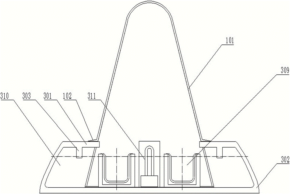
[0014] like figure 1 , figure 2 , image 3 , Figure 4 As shown, a multifunctional electronic insect killer of the present invention includes a bowl-shaped tray 302, and the bowl-shaped tray 302 is provided with a bait storage box 309, and the bait storage box 309 is provided with a mosquito lamp 311. The tray 302 is equipped with an AC input line 308, an AC power indicator light 305, a mosquito lamp switch 304, an AC switch 306, and an AC output line 307; the bowl-shaped tray 302 and the bait storage box 309 are provided with a ring-shaped dead insect collection. groove 310; the top of the bowl-shaped tray 302 is provided with several extension channels 301, and the bottom of the extension channel 301 is provided with a barrier ring 303; the bait storage box 309 is provided with a cone-shaped high-voltage grid 101, and the cone-shaped The lower edge of the high-voltag...


PUM


Abstract

The invention discloses a multifunctional electronic insect killer. A lure storage box is provided with a mosquito-lured lamp; an alternating current input line, an alternating current power indicator lamp, a mosquito-lured lamp switch, an alternating current switch and an alternating current output line are arranged outside a bowl-shaped tray; an annular dead insect collecting tank is arranged between the bowl-shaped tray and the lure storage box; a plurality of extension channels are arranged at the top of the bowl-shaped tray; a barrier ring is arranged at the bottom of each extension channel; a conical high-voltage grid is arranged on the lure storage box; an opening corresponding to each extension channel is formed in the lower edge of the conical high-voltage grid; an opening brim is arranged on each opening correspondingly; a handle-shaped conversion interface is formed in one side of the conical high-voltage grid; a direct current to alternating current conversion switch, an alternating current connecting socket and a high-voltage electronic device are arranged on the handle-shaped conversion interface; the alternating current connecting socket is connected to the alternating current output line; the handle-shaped conversion interface is externally connected with a power storage handle. The multifunctional electronic insect killer is reasonable in structure, simple and convenient to operate, safe, environmentally friendly, economical and practical.

Description

technical field [0001] The invention relates to a pest killing device, in particular to a multifunctional electronic insect killer. Background technique [0002] In spring, summer and autumn, there are often pests in the home environment, especially in summer, which is the active season of various pests. Mosquito and fly bites, cockroaches and other pests invade life, spread diseases and endanger health. Chemical killing used to be the most commonly used method. Although the effect is good, due to certain pollution, with the improvement of people's health and environmental awareness, chemical killing has gradually been neglected. At present, the electronic killing devices that are relatively popular in the market are highly praised. There are mainly two ways to kill insects: active killing and passive killing. The killing efficiency is not high. Passive killing methods, such as mosquito killer lamps, use light sources and odors to lure automatic killing, which is more con...

Claims


Application Information

Patent Timeline
Patent Type & Authority Patents(China)
IPC IPC(8): A01M1/22A01M1/02A01M3/02
Inventor 鲍硕鲍根华
Owner DONGGUAN LEAYARDLE PEST CONTROL TECH
Learn More