Automatic detection system and detection method for mobile phone camera

A mobile phone camera, automatic detection technology, applied in the direction of telephone communication, electrical components, branch equipment, etc., can solve the problems of inability to quantify the color distribution and grayscale changes of pictures, no computer system connection, and inability to save detection data, etc., to achieve detection efficiency. and improve the accuracy, reduce the photo error, and ensure the effect of the display effect

Inactive Publication Date: 2014-10-15
赛龙通信技术(深圳)有限公司
View PDF3 Cites 33 Cited by
  • Summary
  • Abstract
  • Description
  • Claims
  • Application Information

AI Technical Summary

Problems solved by technology

[0004] 1. The existing mobile phone camera detects the images taken by manually holding the mobile phone, and then manually judges whether the captured images are clear or not. The inconsistency of the captured images due to hand shaking can easily lead to misjudgment. This kind of judgment method is highly subjective and easy to make mistakes Judgment, low production efficiency
[0005] 2. Existing mobile phone camera detection adopts subjective judgment of whether the image is clear by shooting a single picture card. During the detection process, the picture card needs to be changed according to the detected items. This judgment method is highly subjective, easy to misjudgment, and low in production efficiency.
[0006] 3. Existing mobile phone camera detection cannot quantify the color distribution and grayscale changes of the picture through the detection equipment, and cannot save the detection data for analysis by technicians
[0007] 4. The existing mobile phone camera detection equipment is a single device that does not use a powerful computer for system connection, and cannot effectively carry out factory manufacturing execution management

Method used


Image

  • Automatic detection system and detection method for mobile phone camera
  • Automatic detection system and detection method for mobile phone camera
  • Automatic detection system and detection method for mobile phone camera

Examples


Embodiment Construction

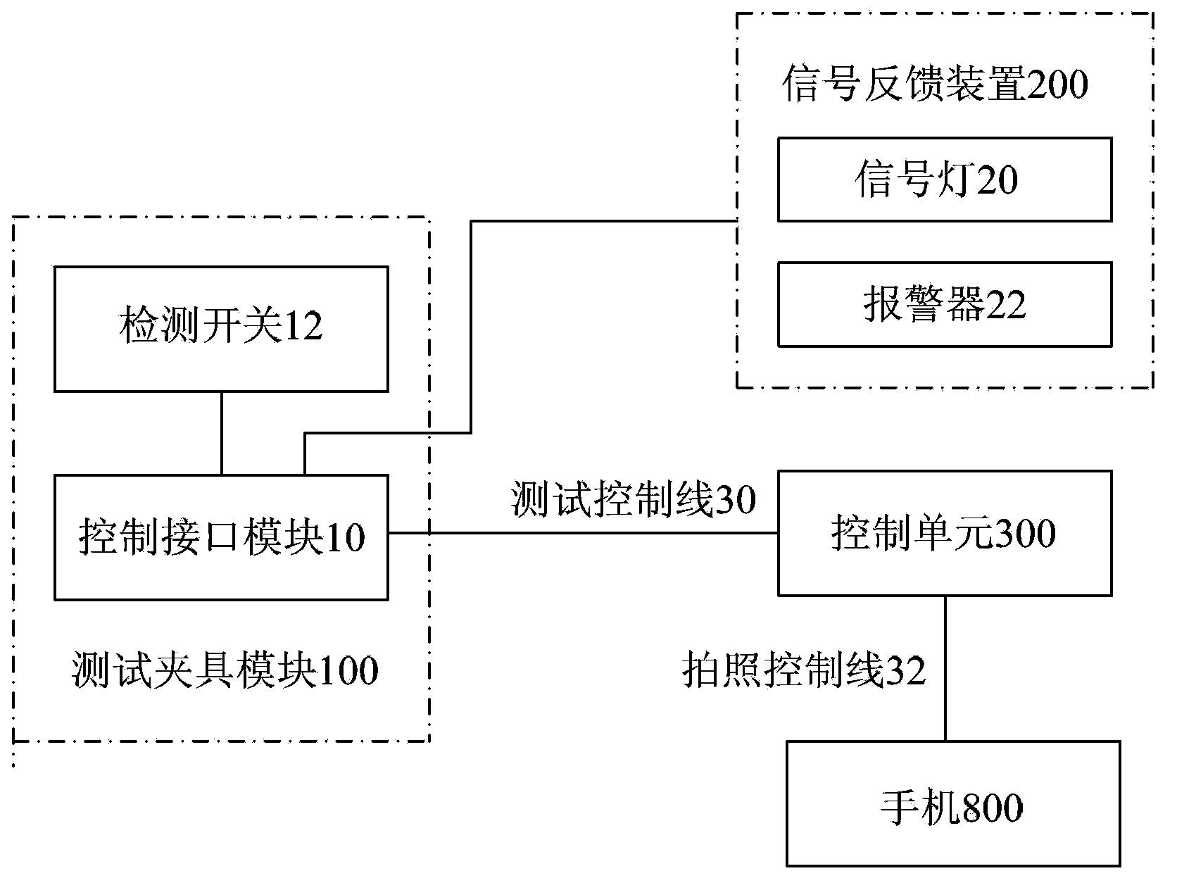
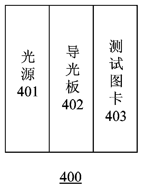
[0040] Reference figure 1 with figure 2 As shown, the present invention provides an automatic detection system for a mobile phone camera, which includes: a test fixture module 100, which is used to place the mobile phone 1, and is provided with a control interface module 10, which is used to control the output feedback and direction of test results The control unit feeds back the detection switch signal; the signal feedback device 200 is used to derive the test result; the control unit 300 is the test control terminal and the test image comparison terminal, and is electrically connected to the control interface module 10 through the test control line 30 to control the test The control unit 300 is electrically connected to the mobile phone through the camera control line 32 to send the camera command and feed back the captured test image; the test pattern card module 400 is opposite to the test fixture module 100 , Used for camera comparison. When a mobile phone with a camera i...


PUM


Abstract

Disclosed is an automatic detection system for a mobile phone camera. The system comprises a test clamp module for placing a mobile phone; a signal feedback device for leading out a test result; a control unit which is electrically connected with the test clamp module through a test control line so as to control a test to start or end and output whether the test result is qualified and is eclectically connected with the mobile phone through a shooting control line so as to send a shooting instruction and feed a shot test image; and a test cart card module which is opposite to the test clamp module for shooting and comparison of the camera. The mobile phone is placed on the test clamp module, a control interface module sends a signal to be detected to the control unit, the control unit sends a test starting instruction to the mobile phone through the shooting control line so as to drive the mobile phone to start a test, after the test card chart module is shot, the mobile phone transmits a detected image to the control unit through the shooting control line for comparison calibration, and the control unit, according to a comparison analysis result, gives a feedback to a signal feedback device so as to output and display whether the test result is qualified.

Description

Technical field [0001] The invention relates to the field of mobile phone testing, in particular to an automatic detection system and a detection method used for a mobile phone camera. Background technique [0002] With the rapid development of mobile communication technology, consumers have higher and higher requirements for mobile terminals. Manufacturers have put forward their own characteristic selling points, including improving the camera shooting effect of mobile terminals. There are many kinds of mobile terminals, including mobile phones, tablet computers, video phones, car navigators, etc. Among them, smart phones pay more attention to the camera shooting effect. In the factory manufacturing process, the addition of camera detection tests can ensure the shooting quality of the mobile terminal. However, as the scale of mobile terminal manufacturing becomes larger and larger, the cost of human resources is getting higher and higher. Only by reducing the cost of testing a...

Claims


Application Information

Patent Timeline
Patent Type & Authority Applications(China)
IPC IPC(8): H04M1/24
Inventor 叶德潜
Owner 赛龙通信技术(深圳)有限公司
Why Eureka
Try Eureka