
A profiled airfoil

A wing and airfoil technology, applied in the field of aircraft, can solve the problems of limited range of effective angle of attack, unstable aerodynamic performance, and low efficiency

Active Publication Date: 2016-02-17
SUZHOU MAICHUANG INFORMATION TECH
View PDF6 Cites 0 Cited by
  • Summary
  • Abstract
  • Description
  • Claims
  • Application Information

AI Technical Summary

Problems solved by technology

[0002] The leading edge of the traditional wing is mostly straight, and the airfoils on the same wing are basically the same everywhere, and the plane shape of the wing is rectangular or trapezoidal, which can generate lift, but the efficiency is not high, and the range of effective angle of attack is not large , the aerodynamic performance is not stable enough, it is difficult to adapt to a variety of different weather conditions

Method used


Image

  • A profiled airfoil

Examples


Embodiment Construction

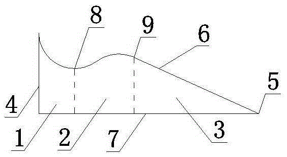
[0009] now attached figure 1 The present invention is specifically described: a special-shaped wing airfoil, comprising a leading edge 6, an upper surface, a lower surface, a trailing edge 7, a wing root 4, a wing tip 5 and a wing body. The leading edge 6 is an oblique S-shaped curve plus a straight line, like a spoon, and the handle of the spoon is the straight line part towards the wingtip 5 direction. The change rule of the distance from the leading edge 6 from the wing root 4 to the wing tip 5 to the trailing edge 7 is: the leading edge 6 at the wing root 4 is farthest from the trailing edge 7, and then slides along the curve to a later point and then moves forward After reaching the earlier point, follow the curve and then connect a straight line until the wing tip 5, thus forming a backward valley and a forward peak, which is equivalent to a large sawtooth. Compared with the traditional wing aerodynamic The performance is greatly improved; the trailing edge 7 is straigh...


PUM


Abstract

The invention discloses a special-shaped wing profile, belongs to the technical field of air vehicles and particularly relates to a wing. The special-shaped wing profile comprises a leading edge, an upper surface, a lower surface, a trailing edge, a wing root, a wing tip and a wing body, wherein the leading edge is a combination of an oblique S-shaped curve and a straight line, the trailing edge is straight, and the wing tip is sharp. A wing is divided into three portions by a plane parallel to the wing root end face along the wingspan direction: the first portion refers to a portion close to the wing root and is roughly a profile with a convex upper and a flat lower and with medial relative thickness, the radius of the leading edge is medial, and a position with maximum thickness is in the back; a second portion refers to a middle portion and is a thick profile with a convex upper and a concave lower, the radius of the leading edge is large, and a position with maximum thickness is in the front; a third portion is a portion close to the wing tip and is roughly a thin profile with double convex surfaces, the radius of the leading edge is small, and a position with maximum thickness is in the middle; the three portions are in smooth connection. The wing with the special-shaped wing profile is large in effective incidence, less prone to stalling and high in efficiency.

Description

technical field [0001] A special-shaped wing airfoil belongs to the technical field of aircraft, and in particular relates to a lift-generating wing. Background technique [0002] The leading edge of the traditional wing is mostly straight, and the airfoils on the same wing are basically the same everywhere, and the plane shape of the wing is rectangular or trapezoidal, which can generate lift, but the efficiency is not high, and the range of effective angle of attack is not large , the aerodynamic performance is not stable enough, and it is difficult to adapt to a variety of different weather conditions. Contents of the invention [0003] The purpose of the present invention is to overcome the above-mentioned deficiency of traditional wing, invent a kind of compound special-shaped wing airfoil. [0004] A special-shaped wing airfoil comprises a leading edge, an upper surface, a lower surface, a trailing edge, a wing root, a wing tip and a wing body. The leading edge is ...

Claims


Application Information

Patent Timeline
Patent Type & Authority Patents(China)
IPC IPC(8): B64C3/10
Inventor 王志成
Owner SUZHOU MAICHUANG INFORMATION TECH
Learn More