
Oil leakage-free and low-noise rotor driving mechanism of vacuum pump

A driving mechanism and vacuum pump technology, which is applied in the direction of machines/engines, liquid fuel engines, pumping devices for elastic fluids, etc., and can solve the oil leakage noise of the vacuum pump, the aging of the sealing ring 5, and the easy wear of the sealing ring, etc. problems, to achieve the effect of avoiding oil leakage

Inactive Publication Date: 2014-10-08
万英南
View PDF5 Cites 0 Cited by
  • Summary
  • Abstract
  • Description
  • Claims
  • Application Information

AI Technical Summary

Problems solved by technology

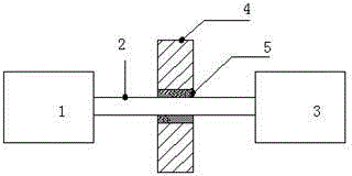
[0004] 1. The shaft 2 runs continuously for a long time, and the sealing ring 5 is easy to wear
[0005] 2. The sealing ring 5 is prone to aging
[0006] 3. The friction between shaft 2 and sealing ring 5 produces noise
[0007] The above drawbacks ultimately result in oil leakage and high noise from the vacuum pump.

Method used


Image

  • Oil leakage-free and low-noise rotor driving mechanism of vacuum pump
  • Oil leakage-free and low-noise rotor driving mechanism of vacuum pump

Examples


Embodiment Construction

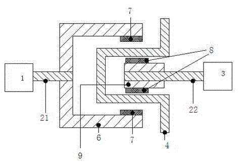
[0019] see figure 2 , which is an oil-leakage-free, low-noise rotor drive mechanism in a vacuum pump of the present invention. As shown in the figure: it includes a motor 1, a shaft and a rotor 3; the motor 1 is connected to a connecting body 6 through a first shaft 21, a first magnet 7 is installed inside the connecting body 6, and the vacuum pump housing 4 is arranged on the first magnet 7, between the housing walls of the vacuum pump housing 4 between the first magnets 7, there is also a second shaft 22 on which a second magnet 8 is installed, and one end of the second shaft 9 is connected to the rotor 3; the second magnet The position of 8 corresponds to the position of the first magnet 7 .

[0020] When the present invention is in use, the first shaft 21 is driven by the motor 1 to rotate, and the first shaft 21 further drives the connecting body 6 to rotate. Due to the magnetic force coupling between the first magnet 7 and the second magnet 8, the shaft attachment 9 is...


PUM


Abstract

The invention relates to a vacuum pump and particularly relates to an oil leakage-free and low-noise rotor driving mechanism of a vacuum pump. The rotor driving mechanism comprises a motor, a shaft and a rotor, and is characterized in that the motor is connected with a connecting body through a first shaft; first magnets are arranged at the inner side of the connecting body; a vacuum pump shell is arranged between the first magnets; a second shaft provided with second magnets is arranged between the shell walls of the vacuum pump shell between the first magnets; one end of the second shaft is connected with the rotor; the position of the second magnet is corresponding to that of the first magnet. According to the oil leakage-free and low-noise rotor driving mechanism of the vacuum pump, magnetic coupling is used for motion transmission and the problem that oil leakage occurs in a traditional oil seal method is avoided.

Description

technical field [0001] The invention relates to a vacuum pump, in particular to a rotor driving mechanism in a vacuum pump without oil leakage and low noise. Background technique [0002] The structure of the rotor drive mechanism in a traditional mechanical vacuum pump is shown in figure 1 . As shown in the figure: the motor 1 drives the rotor 3 to rotate through the connection of the rigid shaft 2 to transmit the motion. The sealing ring 5 is used to seal between the shaft 2 and the vacuum pump housing 4 . [0003] The disadvantages of this seal are: [0004] 1. The shaft 2 runs continuously for a long time, and the sealing ring 5 is easy to wear. [0005] 2. The sealing ring 5 is prone to aging. [0006] 3. The friction between shaft 2 and sealing ring 5 produces noise. [0007] The consequences of the above-mentioned drawbacks are oil leakage and high noise of the vacuum pump. Contents of the invention [0008] The purpose of the present invention is to provide ...

Claims


Application Information

Patent Timeline
Patent Type & Authority Applications(China)
IPC IPC(8): F04C23/02F04C25/02F04C29/06
Inventor 万英南
Owner 万英南
Learn More