
Engineering vehicle and engine rotating speed control system and method thereof

A technology of engine speed and engineering vehicles, which is applied in engine control, machine/engine, electrical control, etc., can solve the problems of large number of sensors, high cost, high failure rate, etc., to reduce fuel consumption, realize simple and reliable, and save energy Effect

Active Publication Date: 2014-10-08
SANY AUTOMOBILE HOISTING MACHINERY
View PDF6 Cites 7 Cited by
  • Summary
  • Abstract
  • Description
  • Claims
  • Application Information

AI Technical Summary

Problems solved by technology

This method needs to install pressure sensors and flow sensors at each oil pump, measure the pressure and flow output by each oil pump, and then calculate the load of each oil pump. The number of sensors is large, and there are disadvantages such as high cost and high failure rate.

Method used


Image

  • Engineering vehicle and engine rotating speed control system and method thereof
  • Engineering vehicle and engine rotating speed control system and method thereof

Examples


Embodiment Construction

[0020] It should be noted that, in the case of no conflict, the embodiments of the present invention and the features in the embodiments can be combined with each other. The present invention will be described in detail below with reference to the accompanying drawings and examples.

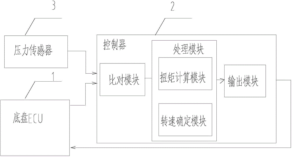
[0021] figure 1 A schematic structural diagram of an engine speed control system of an engineering vehicle provided in an embodiment of the present invention; figure 1 As shown, the engine speed control system includes: chassis ECU (Electronic Control Unit, electronic control unit) 1, used to send the first message including the current torque percentage, and receive the second message including the set speed, wherein, The current torque percentage is equal to the ratio of the current torque of the engine to the limit torque of the engine, so the current torque can be determined by calculating the product of the current torque percentage and the limit torque of the engine; the controller 2 is us...


PUM


Abstract

The invention discloses an engineering vehicle and an engine rotating speed control system and method of the vehicle. The engine rotating speed control system of the engineering vehicle comprises a chassis ECU and a controller, wherein the chassis ECU is used for sending a first message including the current torque percentage and receiving a second message including set rotating speed, the controller is used for being in signal connection with the chassis ECU, receiving the first message and calculating the current torque according to the current torque percentage, the set rotating speed corresponding to the current torque is determined according to a preset mapping table of torques corresponding to rotating speeds, and the second message including the set rotating speed is sent to the chassis ECU. The engine rotating speed control system of the engineering vehicle can avoid giant fuel consumption in the low load, saves energy and is simple and reliable.

Description

technical field [0001] The invention relates to the field of engineering vehicles, in particular to an engineering vehicle and its engine speed control system and method. Background technique [0002] As the power source of the whole machine, the diesel engine needs to provide power for chassis accessories (air conditioners, etc.), diesel engine accessories (fans, steering pumps, etc.), on-board oil pumps (variable pumps, quantitative pumps, etc.), and these powers are dynamic. It varies from tens to hundreds of Nm. For example, after the air conditioner is started, the power used will change according to the temperature change, which will easily cause the diesel engine to stall. [0003] At present, an ideal solution is to install multiple sensors to obtain the dynamic changes in power or power of each component, and then obtain the load change of the diesel engine. However, this solution is difficult to implement, and even if it is implemented, it will cause costs The cos...

Claims


Application Information

Patent Timeline
IPC IPC(8): F02D29/02F02D41/02
Inventor 左光群丁宇王磊
Owner SANY AUTOMOBILE HOISTING MACHINERY
Learn More