
Automatic nozzle cleaning device and method

A technology of automatic cleaning and nozzle mounting plate, which is applied in printing and other directions, can solve the problems that the printing unit cannot automatically clean the nozzle, affect the quality of the printing picture, and cannot realize automatic cleaning, so as to ensure the quality of the printing picture, reduce disconnection and save time. Effect

Active Publication Date: 2016-09-14
杜怀月
View PDF10 Cites 0 Cited by
  • Summary
  • Abstract
  • Description
  • Claims
  • Application Information

AI Technical Summary

Problems solved by technology

The printing unit cannot automatically clean the nozzles, and cannot maintain the nozzles. Due to the environment, paper powder, toner powder, dust particles and other sundries, the nozzles are prone to clogging, which affects the quality of the printing image.
When it is necessary to clean the print head, it needs to be shut down for maintenance, and the nozzle needs to be wiped manually, which is troublesome to clean up, reduces production efficiency, and cannot realize the automatic cleaning function of the print head in the past

Method used


Image

  • Automatic nozzle cleaning device and method
  • Automatic nozzle cleaning device and method
  • Automatic nozzle cleaning device and method

Examples


Embodiment 1

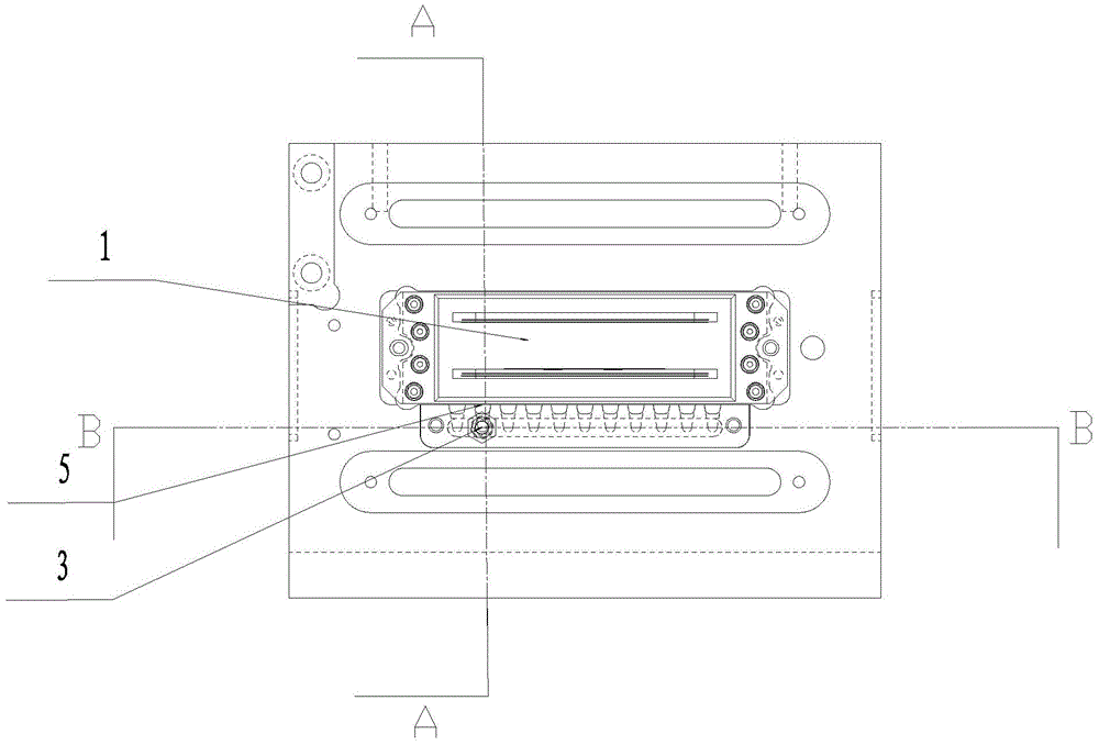
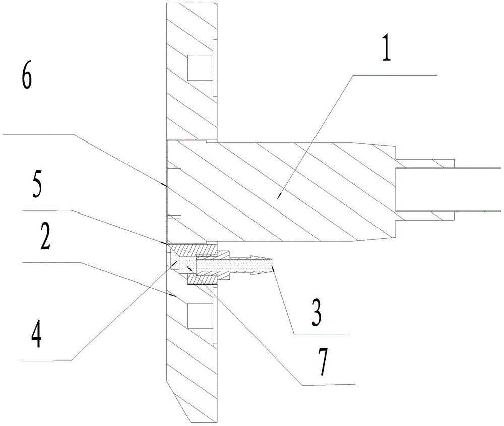
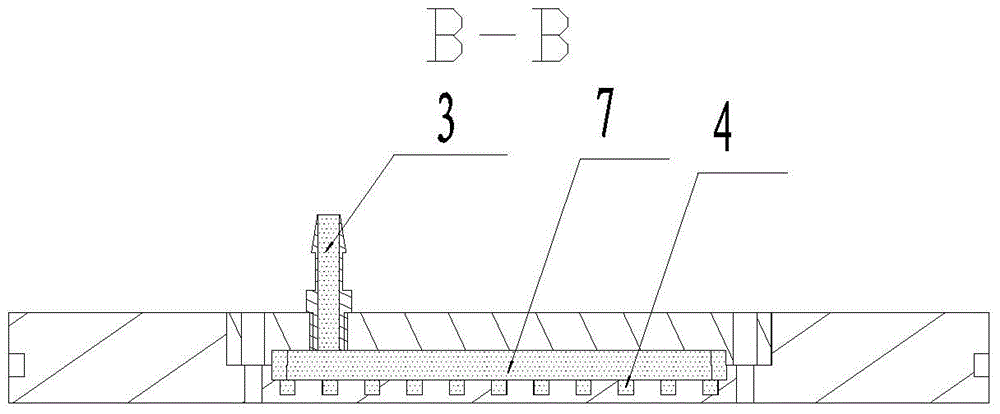
[0020] Such as Figure 1 to Figure 3 As shown, the nozzle automatic cleaning device includes a printing nozzle 1, a nozzle mounting plate 2 and an air blowing device. The printing nozzle 1 is fixed on the nozzle mounting plate 2, and the air blowing device is located on the nozzle mounting plate 2. The air blowing device includes Air hole 3, air blowing hole 4 and air pump, air intake hole 3 is positioned at the right below the shower head, and described air inlet hole 3 comprises air nozzle and strip-shaped airflow channel 7, and described air nozzle is connected with strip-shaped airflow channel 7 Through, the air blowing holes 4 are a plurality of holes located in the nozzle mounting plate 2, the holes are located directly below the nozzle mounting plate 2, and they communicate with the strip-shaped air flow channels 7 respectively, and the holes The opening tends to become smaller along the airway direction of the airflow, and there are one or more stages of structures wit...

Embodiment 2

[0022] Nozzle automatic cleaning device, including printing nozzle 1, nozzle mounting plate 2, blowing device and blowing device fixing plate, printing nozzle 1 is fixed on the nozzle mounting plate 2, and the blowing device is fixed on the fixing plate of the blowing device. Nozzle 1 is opposite, and described air blowing device comprises air inlet 3, air blowing hole 4 and air pump, and described air pump will be pressed in the air inlet 3, and the gas in air inlet 3 flows into air blowing hole 4, and the gas in air blowing hole 4 The airflow is blowing directly to the print head 1 from the narrow air hole 5 to the nozzle surface 6 of the print head.

Embodiment 3

[0024] An automatic nozzle cleaning method, printing with a printing nozzle fixed on a nozzle mounting plate, and blowing air at the printing nozzle through an air blowing device located on the nozzle mounting plate, the specific blowing steps are as follows: the air is pressed into the In the air inlet hole, the gas in the air inlet hole flows into the air blow hole, and the gas in the air blow hole is blown out from the long and narrow air hole, and the air flow blown out is blown toward the nozzle surface parallel to the print head. Through the air flow, impurities such as paper powder, toner powder, and dust particles on the surface of the nozzle are removed, so as to realize the automatic cleaning method of the nozzle. The air intake hole adopts an air nozzle and a long strip air flow channel, the gas entering the air intake hole flows through the air nozzle and enters the long strip air flow channel, and the air blow hole is located directly below the nozzle mounting plat...


PUM


Abstract

The present invention relates to a nozzle automatic cleaning device and method, comprising a printing nozzle, a nozzle mounting plate and an air blowing device, the printing nozzle is fixed on the nozzle mounting plate, the air blowing device is located on the nozzle mounting plate, and the air blowing device includes an air inlet hole and an air blowing hole And the air pump, the air pump is connected with the air inlet, the air inlet is connected with the air outlet, the air blow hole is provided with a long and narrow air hole, and the gas is blown out from the long and narrow air hole of the air blow hole. A method for removing impurities such as paper powder, toner, and dust particles on the surface of the nozzle. An automatic cleaning device is added to the nozzle mounting plate, which is efficient, clean, and will not cause damage to the nozzle. Through the air blowing principle of the air blowing hole on the nozzle mounting plate, the paper powder, toner, dust particles and other sundries on the surface of the nozzle are blown away. No need to stop the machine, no need to manually wipe the nozzle, timely maintenance, simple and easy to operate. Reduce the interruption of the nozzle printing process, ensure the normal operation of printing, improve production efficiency, and ensure the quality of printing images.

Description

technical field [0001] The patent of the invention relates to a printing nozzle cleaning device and method in the fields of inkjet printing, digital printing, ceramic inkjet printing, advertising inkjet printing, and textile digital printing. Background technique [0002] The bottom of the print head mounting plate in the printing unit is flat without any gaps. Its function is to control and fix the position of the nozzle during printing, and connect with the whole printing unit to maintain the consistency of printing work. The printing unit cannot automatically clean the nozzles, and cannot maintain the nozzles. Due to the environment, paper powder, toner powder, dust particles and other sundries, the nozzles are prone to clogging, which affects the quality of the printing image. When the printing nozzle needs to be cleaned, it needs to be shut down for maintenance, and the nozzle needs to be wiped manually, which is troublesome to clean up, reduces production efficiency, ...

Claims


Application Information

Patent Timeline
Patent Type & Authority Patents(China)
IPC IPC(8): B41J2/165
Inventor 杜怀月
Owner 杜怀月
Learn More