Telescopic ultrasonic welding fixture base and ultrasonic welding fixture
An ultrasonic welding and tooling technology, applied in welding equipment, manufacturing tools, non-electric welding equipment, etc., can solve problems such as damage to welding heads and ultrasonic machines, repeated debugging of machines, poor product quality stability, etc., to reduce adjustment time and improve. Stability and welding efficiency, the effect of reducing the number of production
- Summary
- Abstract
- Description
- Claims
- Application Information
AI Technical Summary
Problems solved by technology
Method used
Image
Examples
Embodiment 1
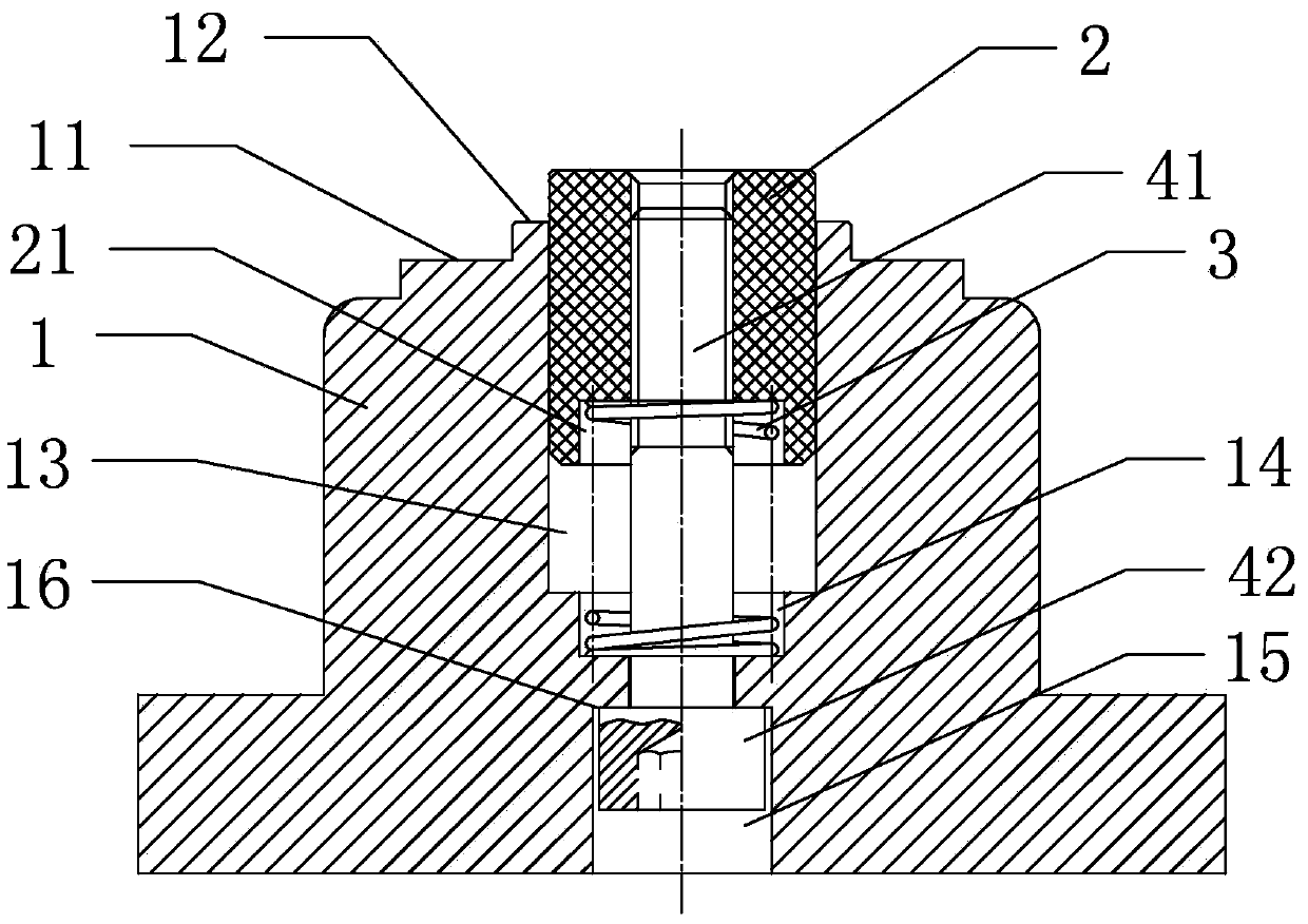
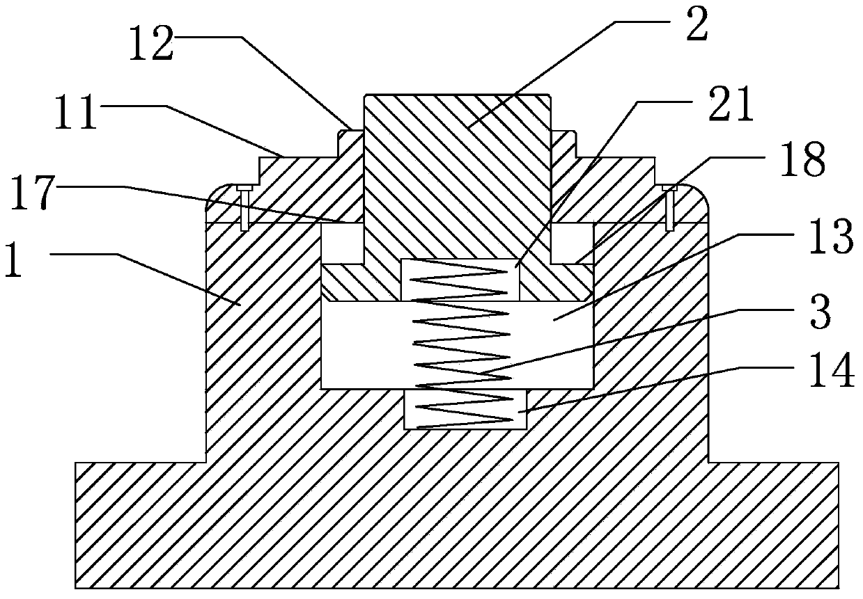
[0019] Such as figure 2 As shown, a telescopic ultrasonic welding tooling base includes a base body 1, the side of the base body has a stepped surface I11, the top of the base body 1 has a placement surface 12, and the base body 1 has a hollow cavity 13, the hollow cavity 13 The top is open, and the placement surface 12 is arranged around the top opening of the hollow cavity 13 to form a circle. The hollow cavity 13 is covered with a central shaft 2, and the hollow cavity 13 has a spring 3 inside. The bottom wall of the hollow cavity 13 has a concave groove I14 , the bottom end of the spring 3 extends into the groove I14 and is supported on the bottom end face of the groove I14, the bottom end of the spring 3 is radially limited in the groove I14, and the top end of the spring 3 is against the center axis 2 The bottom, preferably the bottom of the central axis 2 has a groove II 21, the top of the spring 3 is in the groove II 21, the top of the spring 3 is radially limited in ...
Embodiment 2
[0023] Such as image 3 As shown, the structure is basically the same as that of Embodiment 1, the difference is that no bolts are set in this structure, but a stepped surface III17 is set on the inner wall surface of the hollow cavity 13, wherein, preferably, the base body 1 is composed of upper and lower parts, and the steps The surface III17 is formed by the junction of the upper and lower parts, which is convenient for manufacturing the cross-sectional area of the hollow cavity part below the stepped surface III17 is larger than the cross-sectional area of the hollow cavity part above the stepped surface III17. A stepped surface IV18 is set on the outer wall of the central axis 2, and the step The cross-sectional area of the central axis part below the surface IV18 is larger than the cross-sectional area of the central axis part above the stepped surface III17, and the central axis 2 is limited in the hollow cavity 13 of the base body 1 by the structure of the stepp...
Embodiment 3
[0025] Such as Figure 4 As shown, the ultrasonic welding tooling includes a base and a welding head 5. The base adopts the scalable ultrasonic welding tooling base described in Embodiment 1. The bottom surface of the welding head 5 is a plane, and the welding head 5 is installed on a lifting mechanism for scalable ultrasonic welding. The base of the tooling is located under the welding head 5. When welding starts, the welding head 5 descends and presses down on the central axis 2, and the spring gradually shortens downward until the flat part of the welding head touches the seal 7 and gradually moves downward to weld the seal on On the filter end cover 6. Compared with the ultrasonic welding tool with traditional structure, the welding head is changed from a concave structure to a flat structure, and the base is changed from a three-step integral structure to a two-step split structure. The central axis, when the ultrasonic machine is welding, the central axis 2 can be stret...
PUM
 Abstract
Description
Claims
Application Information
 - R&D
- Intellectual Property
- Life Sciences
- Materials
- Tech Scout
- Unparalleled Data Quality
- Higher Quality Content
- 60% Fewer Hallucinations
Browse by: Latest US Patents, China's latest patents, Technical Efficacy Thesaurus, Application Domain, Technology Topic, Popular Technical Reports.
© 2025 PatSnap. All rights reserved.Legal|Privacy policy|Modern Slavery Act Transparency Statement|Sitemap|About US| Contact US: help@patsnap.com


