
Stirrer

A mixer and mixing mechanism technology, applied to mixer accessories, mixers with rotating mixing devices, mixers, etc., can solve the problems of high labor cost, low efficiency, and uneven mixing, so as to improve the mixing effect and increase production Efficiency, material mixing effect

Inactive Publication Date: 2014-10-08
SUZHOU CHUANGWEISHENG AUTOMATION SCI & TECH
View PDF5 Cites 8 Cited by
  • Summary
  • Abstract
  • Description
  • Claims
  • Application Information

AI Technical Summary

Problems solved by technology

[0002] With the continuous development of science and technology, people's awareness of food quality has been continuously strengthened, and the requirements for the degree of mixing and homogenization of food are getting higher and higher. At the same time, the country has also issued relevant quality standards. The proportion of phases has been clearly stipulated, so that the products produced by many enterprises cannot meet the national quality standards. On the other hand, because the degree of automation is too low, the labor cost is high, and the efficiency is not high, so many enterprises have to quit. Therefore, the food processing technology must be continuously innovated in order to catch up with people's demand awareness and meet the national quality control standards; the current common food mixer is generally fixed with a blade, which is fixedly connected with the stirring shaft. When making different foods, different sets of mixing blades need to be used, which requires multiple mixers, resulting in a waste of space and resources. At the same time, the raw materials of the current food mixer are mixed directly after entering the feed port, and the effect is not good. , due to uneven stirring, the ratio of solid phase and liquid phase is out of balance

Method used


Image

  • Stirrer
  • Stirrer
  • Stirrer

Examples


Embodiment Construction

[0014] The following will clearly and completely describe the technical solutions in the embodiments of the present invention with reference to the accompanying drawings in the embodiments of the present invention. Obviously, the described embodiments are only some, not all, embodiments of the present invention. Based on the embodiments of the present invention, all other embodiments obtained by persons of ordinary skill in the art without making creative efforts belong to the protection scope of the present invention.

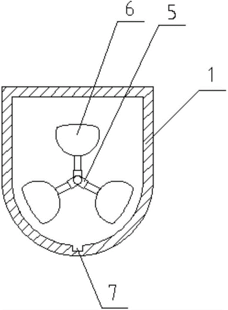
[0015] see Figure 1-3 , in the embodiment of the present invention, a kind of agitator comprises stirring container 1, driving mechanism and stirring mechanism; Said stirring container 1 is provided with feed inlet 14 and discharge outlet 16 respectively above and below, and described feed inlet 14 below Two hob wheels 15 are arranged horizontally, a cover body 17 is provided on the feed port 14, a stirring tank 7 is provided at the bottom of the inside of th...


PUM


Abstract

The invention discloses a stirrer. The stirrer comprises a stirring container, a driving mechanism and a stirring mechanism, wherein the upper part and the lower part of the stirrer are respectively provided with a material inlet and a material outlet; the driving mechanism comprises a driven wheel, a driving wheel, a speed regulator, a motor and an electric control cabinet; the stirring mechanism comprises a main shaft, spiral blades and blades; the spiral blades and the blades are fixedly connected to the main shaft; the stirrer can enable materials to be stirred relatively uniformly; the materials are relatively pure in flavor; the percent of pass of foods is ensured; secondarily, the spiral blades not only enable the materials to be mixed relatively fully, but also can push and guide the materials; the material discharge is convenient; the production efficiency is improved greatly; manufacturing needs of the different foods can be met by replacing the dismountable blades; hobbing cutter wheels with cutting blades are installed at the lower part of the material inlet, and can be used for cutting the raw materials entering a stirring groove, and then the cut raw materials are stirred, and the stirring effect is improved greatly.

Description

technical field [0001] The invention relates to an automatic food processing device, in particular to a mixer. Background technique [0002] With the continuous development of science and technology, people's awareness of food quality has been continuously strengthened, and the requirements for the degree of mixing and homogenization of food are getting higher and higher. At the same time, the country has also issued relevant quality standards. The proportion of phases has been clearly stipulated, so that the products produced by many enterprises cannot meet the national quality standards. On the other hand, because the degree of automation is too low, the labor cost is high, and the efficiency is not high, so many enterprises have to quit. Therefore, the food processing technology must be continuously innovated in order to catch up with people's demand awareness and meet the national quality control standards; the current common food mixer is generally fixed with a blade, w...

Claims


Application Information

Patent Timeline
IPC IPC(8): B01F7/08B01F7/04B01F15/02
Inventor 田银东
Owner SUZHOU CHUANGWEISHENG AUTOMATION SCI & TECH
Learn More