Valley fill circuit with protection function

A technology of protection function and valley filling circuit, applied in the field of rectification and filtering, can solve the problems of large differential mode conduction interference, decreased power factor of valley filling circuit, poor surge voltage absorption effect, etc. The effect of large factor and good protection performance

Active Publication Date: 2014-10-01
MORNSUN GUANGZHOU SCI & TECH
View PDF10 Cites 7 Cited by
  • Summary
  • Abstract
  • Description
  • Claims
  • Application Information

AI Technical Summary

Problems solved by technology

[0017]2. Poor protection performance
[0028]The shortcoming of the parallel capacitor CL is that the working voltage of the capacitor CL is high; the capacity of the capacitor CL is large, and due to the filtering function, Figure 4 shows the power factor (PF) drop of the traditional valley filling circuit 200 ; The capacity of the capacitor CL is small, and the high-frequency ripple current absorption generated by the flyback circuit 300 of the rear stage is not obvious, which causes the conversion efficiency (η) of the flyback switching power supply circuit to decline, and the external differential mode conduction interference is very large ; Since the capacitor CL needs to absorb high-frequency ripple, if a high-voltage ceramic capacitor is used, because of the piezoelectric effect of the high-voltage ceramic capacitor, the higher the operating voltage, the smaller the capacity...

Method used


Image

  • Valley fill circuit with protection function
  • Valley fill circuit with protection function
  • Valley fill circuit with protection function

Examples


no. 1 example

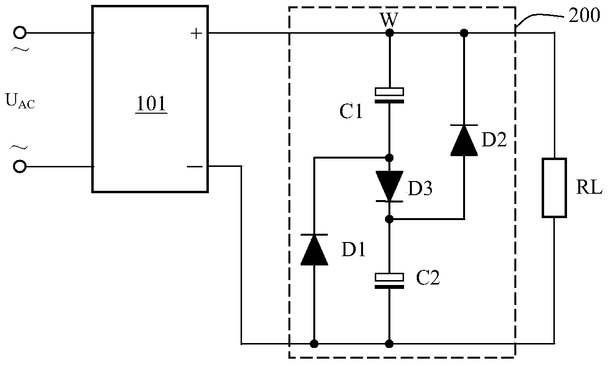
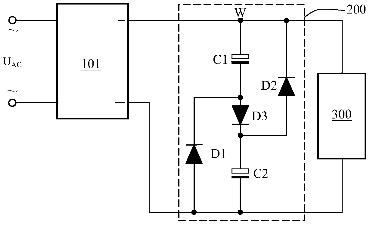
[0057] Figure 5 Shows the principle diagram of the valley filling circuit with protection function of the first embodiment, a valley filling circuit with protection function, which is used to directly connect the AC input U AC , Including valley filling circuit 201, and a rectifier circuit 202 with protection function set in the front stage of valley filling circuit, AC input U AC It has a first terminal 01 and a second terminal 02; connected to the rectifier circuit 202 with protection function, the rectifier circuit 202 with protection function includes two interchangeable input terminals, which are Figure 5 The two ends of the first varistor RV1, and the positive output terminal (V O+ The terminal connected to the second varistor RV2) and the negative output terminal (V O- The terminal connected to the second varistor RV2);

[0058] The valley filling circuit 201 includes a first capacitor C1 and a first diode D1. The anode of the first capacitor C1 is connected to the anode ...

no. 2 example

[0085] Figure 7 Shows the principle diagram of the valley filling circuit with protection function of the second embodiment, a valley filling circuit with protection function, which is used to directly connect the AC input U AC , Including valley filling circuit 201, and a rectifier circuit 202 with protection function set in the front stage of valley filling circuit, AC input U AC It has a first terminal 01 and a second terminal 02; connected to the rectifier circuit 202 with protection function, the rectifier circuit 202 with protection function includes two interchangeable input terminals, which are Figure 7 The two ends of the first varistor RV1, and the positive output terminal (V O+ The terminal connected to the second varistor RV2) and the negative output terminal (V O- The terminal connected to the second varistor RV2);

[0086] The circuit connection relationship of the valley filling circuit 201 is the same as that of the first embodiment, and will not be repeated here...

no. 3 example

[0091] Figure 8 Shows the principle diagram of the valley filling circuit with protection function of the third embodiment, a valley filling circuit with protection function, which is used to directly connect the AC input U AC , Including valley-filling circuit 201’, and a rectifier circuit 202 with protection function set in the front stage of valley-filling circuit, AC input U AC It has a first terminal 01 and a second terminal 02; connected to the rectifier circuit 202 with protection function, the rectifier circuit 202 with protection function includes two interchangeable input terminals, which are Figure 8 Both ends of the medium-voltage sensitive resistor RV1, and the positive output terminal (V O+ The terminal connected to the second varistor RV2) and the negative output terminal (V O- Terminal connected to varistor RV2);

[0092] The difference from the first and second embodiments is that the valley filling circuit 201' also includes a resistor R1, which is connected in...


PUM


Abstract

The invention provides a valley fill circuit with the protection function. A charging diode D3 of an existing valley fill circuit is connected with a third capacitor C3 in parallel, so that the withstand voltage of the third capacitor C3 is a half of the maximum peak of input pulsating direct currents, and high frequency ripple currents of a later-stage switching power source 300 can be fully and effectively absorbed. The front and the back of a rectifier bridge 101 are provided with a multi-stage double-direction filter circuit composed of a voltage dependent resistor RV1, a voltage dependent resistor RV2, a thermistor NTC and a safety capacitor C and a protection circuit composed of an inductor L respectively. The valley fill circuit has the advantages that the power factor is large, the value of the C3 does not influence the power factor, the circuit topology structure is simple, the absorbing effect on surge voltage is good, the cost is low and the size is small. When the later stage is the switching power source, the difference module conducted interference degree accords with the grade of CLASSB in GB9254.

Description

technical field [0001] The invention relates to the field of rectification and filtering, in particular to a valley-filling circuit with a protection function in a switching power supply. Background technique [0002] Industrial and civil use need to change the AC voltage of various power grids into DC. With the further requirements of the national standard on the power factor of electrical appliances, there are power factor requirements for switching power supplies with power consumption above 75W, that is, the operating current of the circuit is required The waveform is basically the same as the voltage waveform. At present, energy-saving lamps above 5W have proposed power factor requirements. [0003] Note: The 75W data comes from the Chinese national standard GB17625.1-1998, named "Limits of Harmonic Current from Low-Voltage Electrical and Electronic Equipment (Input Current ≤ 16A per Phase of Equipment)". [0004] At present, there is a power factor correction circuit...

Claims


Application Information

Patent Timeline
IPC IPC(8): H02M7/00H02M1/14H02M1/42
CPCY02B70/10
Inventor 王保均刘改刘坤明
Owner MORNSUN GUANGZHOU SCI & TECH
Why Eureka
Try Eureka