
A Conjugate Transverse Shear Design Method for Planar Link Mechanism

A planar linkage mechanism and design method technology, applied in calculation, special data processing applications, instruments, etc., can solve problems affecting tool life and unsatisfactory shearing performance

Active Publication Date: 2017-01-25
DALIAN UNIV OF TECH
View PDF1 Cites 0 Cited by
  • Summary
  • Abstract
  • Description
  • Claims
  • Application Information

AI Technical Summary

Problems solved by technology

The rolling shear mechanism designed by the method of given the accurate comprehensive mechanism size parameters of several positions of the upper shear blade and only controlling the trajectory of the dynamic lowest point of the upper shear blade has unsatisfactory shear performance and affects the service life of the tool

Method used


Image

  • A Conjugate Transverse Shear Design Method for Planar Link Mechanism
  • A Conjugate Transverse Shear Design Method for Planar Link Mechanism
  • A Conjugate Transverse Shear Design Method for Planar Link Mechanism

Examples


Embodiment Construction

[0036] The shearing process parameters of a type of rolling shears are shown in Table 1.

[0037] Table 1 shearing process parameters

[0038]

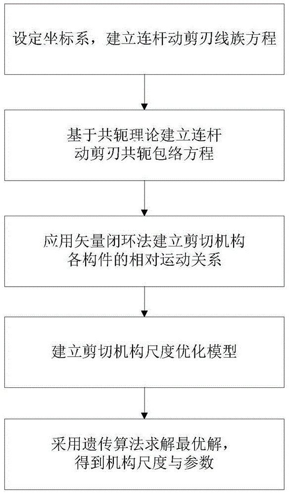
[0039] A design method of conjugate transverse shear of planar linkage mechanism, its operation flow is as follows figure 1 shown. Specifically:

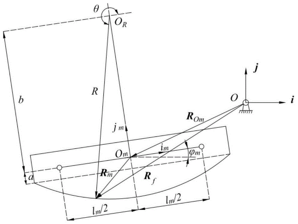
[0040] Step 1: Set the coordinate system of the shearing mechanism and determine the relative relationship of the two degrees of freedom. Such as image 3 shown. Take a fixed hinge point O of the shearing mechanism as the coordinate origin, take the horizontal direction as the x-axis, and the vertical direction as the y-axis to set a fixed coordinate system S f ;Moving coordinate system S m Consolidated on the moving shear blade, a coordinate axis passes through the two hinge points, and takes the middle point l of the two living hinge points m / 2 is the coordinate origin O m . The center of the arc of the scissors is at y m axis; moving coordinate system S m with the set coor...


PUM


Abstract

The invention discloses a method for designing conjugate traverse shearing for a two-degree-of-freedom, and single-ring and double-ring fully-hinged planar linkage mechanism. The method comprises the following steps of: 1) setting a shearing mechanism coordinate system; 2) setting the corner relationship between two motivity members; 3) applying coordinate conversion to establish the line equation of a linkage dynamic shear blade; 4) establishing the conjugate envelope equation of the linkage dynamic shear blade; 5) educing the speed equation of a point on a linkage envelope line; 6) establishing the scale optimization model of the shearing mechanism, taking the minimum fitting error of a dynamic shear blade envelope line and a straight line in a shearing range, and the tendency of the speed of a point on a weighing envelope line to zero as targets, and taking a superposition amount, the opening degree of a non-shearing range, and a linkage length as constraint conditions; 7) solving the optimal solution by a genetic algorithm to obtain the dimensions and parameters of the mechanism. The method is capable of improving shearing quality, ensuring orderliness, no step and no deformation of a shearing section, reducing the scratches and wear of the shear blade, and prolonging the service life of the shear blade.

Description

technical field [0001] The invention relates to a design method of a plane linkage mechanism conjugate transverse shear, which belongs to the technical field of metal plate transverse shear machinery. Background technique [0002] The metal plate transverse shearing mechanism is an important equipment in the heavy plate production line of heavy industry enterprises, and is mainly used to cut the rolled steel plate to length. Its characteristic is that the upper cutting edge of the connecting rod is in the shape of a circular arc, and the fixed lower cutting edge is a straight line segment. Usually, this kind of shearing machine is also called a rolling shear. This kind of shearing machine has the advantages of good cutting quality, high cutting efficiency, long cutting blade life and low transmission power, and is widely used. [0003] In 1971, Sidmona Newman Company (MDN for short) successfully developed the rolling shear mechanism for the first time, and it has been rapid...

Claims


Application Information

Patent Timeline
Patent Type & Authority Patents(China)
IPC IPC(8): G06F17/50
Inventor 王德伦董惠敏孙大庆夏永邱俊黎康康汪全罗婧
Owner DALIAN UNIV OF TECH
Learn More