
A Detection Method of Radar Target Track Based on Correlation Velocity

A detection method and radar target technology, applied in the field of radar, can solve the problems of poor processing effect of undulating target model, poor tracking performance, large noise function value, etc.

Inactive Publication Date: 2017-01-18
XIDIAN UNIV
View PDF8 Cites 0 Cited by
  • Summary
  • Abstract
  • Description
  • Claims
  • Application Information

AI Technical Summary

Problems solved by technology

[0004] Barniv first applied the dynamic programming algorithm to the TBD (Track Before Detect Algorithm) algorithm. In 1993, James Arnold developed an objective function algorithm based on Bayesian theory and using probability density function to optimize the decision-making process, which can detect to the target below 0dB, but this type of algorithm is suitable for non-fluctuating model targets, and the processing effect for the fluctuating target model is poor
Tonissen et al. directly use the amplitude information of the assumed target to construct the objective function, which can detect the moving target of the undulating model. Although this algorithm has good performance in detecting targets, its tracking performance is poor, and the tracking separation problem will directly affect the tracking performance of the algorithm.
The DP-TBD method is applied to multi-frame accumulation due to the many state transitions between radar target frames, resulting in a much larger amount of calculation data than the traditional tracking algorithm. In addition, the DP-TBD algorithm only retains an optimal path in the search window, while At a low SNR, at each stage there may be an association error because the value of the noise function is larger than the value of the target function, or two targets intersect

Method used


Image

  • A Detection Method of Radar Target Track Based on Correlation Velocity
  • A Detection Method of Radar Target Track Based on Correlation Velocity
  • A Detection Method of Radar Target Track Based on Correlation Velocity

Examples


Embodiment Construction

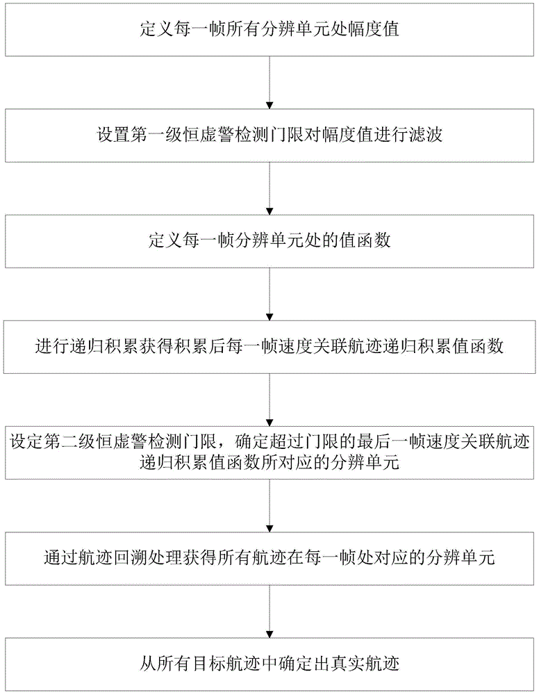
[0053] refer to figure 1 , illustrate a kind of detection method based on the radar target track of correlation speed of the present invention, be used for signal tracking under the low signal-to-noise ratio, comprise the following steps:

[0054] Step 1, the radar transmits signals to scan the monitoring area of ​​the target, and receives the echo data in the monitoring area; the radar receives the echo data by scanning the monitoring area, and takes each scan of the monitoring area as a frame , scan K frames in total, then receive the echo data of K frames;

[0055] Set the monitoring area as an x-y two-dimensional plane in which the target moves, and set the x-axis of the two-dimensional plane to have N x resolution units, the y-axis has N y resolution units, then the amplitude value of the echo data of the kth frame at the resolution unit (i, j) is i=1,...,N x , j=1,...,N y ;

[0056] Among them, the number of frames k∈{1,2,…,K}, where K represents the total number ...


PUM


Abstract

The invention discloses a detection method for radar target tracks on basis of correlation speeds, and relates to the technical field of radars. The method includes the first step of using echo data to obtain amplitude values at corresponding resolution cells, the second step of setting a primary constant false-alarm detection threshold to carry out filtering on the echo data and obtaining the amplitude values after filtering is conducted, the third step of setting value functions of the resolution cells, the fourth step of calculating value functions of speed correlation track recursion accumulation of the accumulated echo data of each frame, the fifth step of setting a secondary detection threshold and obtaining the resolution cells where targets exceeding the threshold are located, the sixth step of conducting backtracking processing on the data to obtain the resolution cells where frames of all tracks are located, and the seventh step of determining true target tracks from all the tracks. A correlation speed algorithm is introduced, the processing data size is reduced, mistaken correlation of the target tracks is reduced, false tracks are reduced, and mechanical multi-target tracking under low an SNR is achieved.

Description

technical field [0001] The invention belongs to the technical field of radar, and relates to a radar target track detection method based on correlation velocity, which is used for signal detection and tracking under low signal-to-noise ratio. Background technique [0002] The basic idea of ​​dynamic programming algorithm is to use multi-stage decision-making strategy to deal with problems hierarchically. DP-TBD (Track Before Detect Algorithm Based on Dynamic Programming, tracking before detection based on dynamic programming) algorithm is applied to the radar system, which obviously changes the detection ability of the radar for weak and small targets. Therefore, DP-TBD has been extensively studied recently. . [0003] The traditional target detection and tracking algorithm is greatly affected by the target SNR, and its detection and tracking performance is obviously restricted under low signal-to-noise ratio. Track-before-detection is an effective method to detect and tra...

Claims


Application Information

Patent Timeline
Patent Type & Authority Patents(China)
IPC IPC(8): G01S13/66G06F19/00
CPCG01S7/415G01S13/66
Inventor 吴建新鲁缘政王彤
Owner XIDIAN UNIV
Learn More