Eureka AIR delivers breakthrough ideas for toughest innovation challenges, trusted by R&D personnel around the world.

Universal sounding lead device

A sounding hammer and universal technology, applied in the direction of measuring devices, instruments, etc., can solve the problems of long strip sounding hammer stuck in bending, unable to complete detection and other problems

Active Publication Date: 2014-10-01
GUANGZHOU SHIPYARD INTERNATIONAL LTD
View PDF4 Cites 5 Cited by
  • Summary
  • Abstract
  • Description
  • Claims
  • Application Information

AI Technical Summary

Problems solved by technology

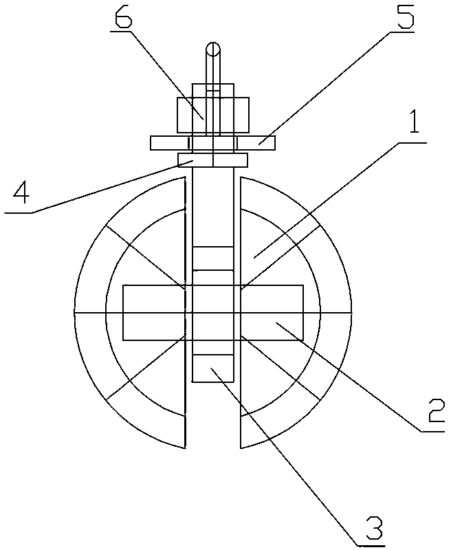
[0005] The universal sounding hammer device of the present invention moves on the sounding pipe through the rolling ball, and the rotating rod on the universal sounding hammer device can swing around the middle rotating shaft of the rolling ball to realize the rolling of the universal sounding hammer device The ball moves back and forth. In addition, the top of the rotating rod is provided with a suspension. The positioning nut limits the suspension between the positioning nut and the limit block so that it cannot move up and down along the rotating rod. The rotating rod runs through the through hole of the suspension. The suspension It can rotate horizontally around the rotating rod. By setting the suspension that can rotate horizontally around the rotating rod and the rolling ball that can move back and forth, it can move in any direction on the sounding pipe. It is not only suitable for the sounding pipe in the vertical section, It can also be applied to continuous and curved sounding pipes, and can complete the detection work on various sounding pipes, effectively solving the problem that the traditional long strip sounding hammer is easy to get stuck in the curved sounding pipe and cannot complete the detection work

Method used


Image

  • Universal sounding lead device

Examples


Embodiment Construction

[0007] Such as figure 1 The universal sounding hammer device shown includes a rolling ball 1, which is formed by connecting two hemispheres through a middle shaft 2, and a rotating rod 3 is provided in the gap between the two hemispheres. The bottom end of the rotary rod is provided with an annular through hole, the middle rotating shaft between the two hemispheres runs through the annular through hole at the bottom end of the rotary rod, the top of the rotary rod is provided with a limit block 4, and the surface of the rotary rod above the limit block 4 is provided with threads. The suspension part 5 is sleeved on the top of the rotating rod through the through hole, and the positioning nut 6 is fixed on the top of the rotating rod by tightening the suspension part between the positioning nut and the limit block. The rotating rod on the universal sounding hammer device can swing around the middle shaft of the rolling ball to realize the forward and backward movement of the ro...


PUM


Abstract

The invention discloses a universal sounding lead device. The universal sounding lead device comprises a rolling sphere. The rolling sphere is formed by connecting two semispheres through a middle rotating shaft. A rotating rod is arranged in the gap between the two semispheres. An annular through hole is formed in the bottom end of the rotating rod. The middle rotating shaft between the two semispheres penetrates through the annular through hole in the bottom end of the rotating rod, a limiting block is arranged at the top end of the rotating rod, and threads are arranged in the position, above the limiting block, of the surface of the rotating rod. A suspension part is arranged at the top end of the rotating rod in a sleeved mode through the through hole. A setscrew nut is screwed to the top end of the rotating rod, so that the suspension part is fixed between the nut and the limiting block. According to the universal sounding lead device, by the arrangement of the suspension part which can horizontally rotate around the rotating rod and the rolling sphere which can move front and back, the universal sounding lead device can move in any direction on sounding pipes; the universal sounding lead device is suitable for sounding pipes on a vertical section and also can be applied to sounding pipes with continuous elbows, and is wide in application range and high in practicality.

Description

technical field [0001] The invention relates to a universal sounding hammer device. Background technique [0002] In order to check the filling and draining of the liquid in the holding tank and the depth of the bilge water, sounding pipes are installed in each ballast tank, fuel tank, cofferdam, clean water tank and other difficult-to-reach sub-compartments of the ship. The existing strip-shaped sounding hammer is only suitable for the sounding pipe of the vertical section of the traditional ship-shaped oil tank, but for the new type of ship, especially the shrinking stern ship, due to the limitation of the hull line shape, the sounding pipe has to be Arranged in a continuous curved pipe, the traditional elongated sounding hammer is difficult to slide down or retract smoothly due to excessive resistance during the descent process, and it is easy to get stuck on the curved sounding pipe and cannot effectively complete the detection work. The traditional strip sounding ...

Claims


Application Information

Patent Timeline
Patent Type & Authority Applications(China)
IPC IPC(8): G01B21/18
Inventor 舒向阳
Owner GUANGZHOU SHIPYARD INTERNATIONAL LTD
Why Eureka
Eureka Blog
Learn More