Eureka AIR delivers breakthrough ideas for toughest innovation challenges, trusted by R&D personnel around the world.

Driving device for safety belt tensioner

A technology for driving devices and safety belts, which is applied in the direction of transmission devices, seat belts in vehicles, belt tighteners, etc., can solve the problems of damage to mechanical properties of meshing components, large meshing force, deformation of meshing components, etc., and achieve a simple and simple structure Effect

Active Publication Date: 2014-10-01
IMS GEAR SE & CO KGAA
View PDF8 Cites 5 Cited by
  • Summary
  • Abstract
  • Description
  • Claims
  • Application Information

AI Technical Summary

Problems solved by technology

Such loads lead to high torques in the driving phase (holding phase) of the belt tensioner, resulting in high meshing forces, especially when the gear members used are external helical gears, resulting in high axial forces, which This high axial force can cause deformation of the meshing components such as the gear body and the bearings in the seat belt tensioner housing, thus possibly leading to reduced stability and ultimately damage to the meshing components and a reduction in mechanical properties

Method used


Image

  • Driving device for safety belt tensioner
  • Driving device for safety belt tensioner
  • Driving device for safety belt tensioner

Examples


Embodiment Construction

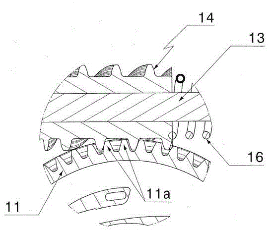
[0047] exist figure 1 In the figure, only the main part of the seat belt tensioning drive device 1 in the device of the present invention is shown, wherein the motor 3 is used as the drive unit. The motor shaft 4 is connected with the main shaft 13 of the worm gear 10 through the transmission device 5, and can tension the winding shaft 4, so that the safety belt 2 is tightly wound around the winding shaft 4. The transmission device 5 is designed as a worm drive, which is composed of a worm 6 mounted on the motor shaft 4 of the motor 3 in a non-rotational connection and a worm wheel 7 matched with the worm 6, wherein the worm wheel 7 is fixedly installed on the main shaft 13 of the worm drive 10 superior. The housing of the belt tensioning drive is in the figure 1 is not shown in .

[0048] The worm drive 10 according to the invention comprises a worm 12 and a driven wheel 11 . The worm 12 is installed on the main shaft 13 and can move in the direction of R under the elasti...


PUM


Abstract

The invention relates to a safety belt tensioner driving device for tightening of a safety belt which can wind around a winding shaft. The safety belt tensioner driving device comprises a main shaft driven by a driving unit and a worm transmission device with a worm and a driven wheel. The worm is installed on the main shaft in a non-rotating mode. The driven wheel is installed on the winding shaft in a non-rotating connecting mode and is engaged with the worm. According to the invention, the worm includes a first tooth segment in the shape of a first toothed gear, and at a first position of the worm, the first tooth segment is engaged with the driven wheel. The worm includes at least one second tooth segment in the shape of a second gear. The second tooth segment is behind the first tooth segment. The shapes of the two tooth segments are designed to be identical. Axial displacement between the first position and the second position occurs to the worm when the worm is under an axial force. At the first position, the worm is engaged with the driven wheel through the first tooth segment. At the second position, the worm is engaged with the driven wheel through the second tooth segment.

Description

technical field [0001] According to the preambles of the claims, the invention relates primarily to a seat belt tensioning drive for tensioning a seat belt that can be wound around a winding shaft. Background technique [0002] Such a reversible belt tightening drive is known from German patent DE102008048339A1, in which an electric motor drives a main shaft via a first transmission (specifically a helical gear transmission) via a second transmission on its side. The second transmission drives a drive wheel non-rotatably mounted on the take-up shaft to wind up the seat belt. This second transmission consists of a screw mounted on the main shaft and an external helical gear that drives the wheels. [0003] The reversible seat belt tensioner is activated in different situations, e.g. in the event of minor or life-threatening impacts, off-road driving or rapid braking and deceleration of the vehicle. tight. To keep the seat belt tensioned in these situations, the electric mo...

Claims


Application Information

Patent Timeline
Patent Type & Authority Applications(China)
IPC IPC(8): F16H35/00
CPCB60R2022/468B60R22/46B60R2022/4666
Inventor A·卢赫特M·科普P·苏尔劳
Owner IMS GEAR SE & CO KGAA
Why Eureka
Eureka Blog
Learn More