
Bracket elements and clutches

A bracket element and clutch technology, applied in clutches, friction clutches, fluid-driven clutches, etc., can solve the problems of clutch wear, deterioration of vibration intensity, damage to clutch separation performance, etc., and achieve the effect of improving installability

Active Publication Date: 2018-03-30
SCHAEFFLER TECH AG & CO KG
View PDF8 Cites 0 Cited by
  • Summary
  • Abstract
  • Description
  • Claims
  • Application Information

AI Technical Summary

Problems solved by technology

The disengagement performance of the clutch can be impaired by the scalloping effect, which, in addition, can worsen the wear and shock intensity of the clutch

Method used


Image

  • Bracket elements and clutches
  • Bracket elements and clutches
  • Bracket elements and clutches

Examples


Embodiment Construction

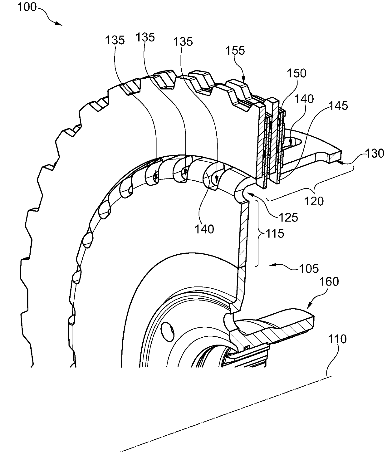
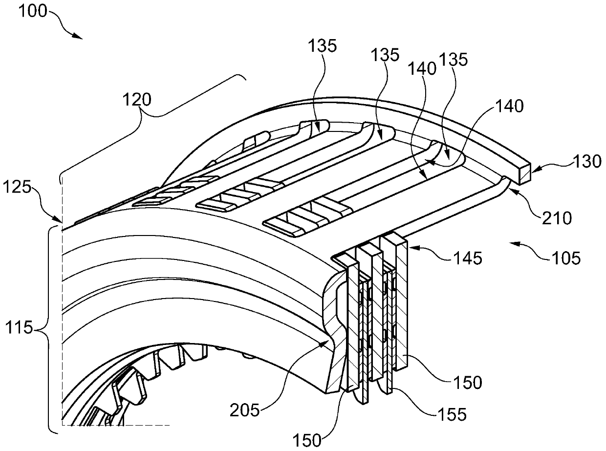
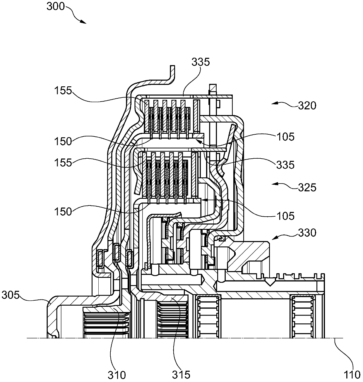
[0027] with the help of figure 1 The present invention is explained in detail by taking the friction disc clutch 100 as an example. figure 1 The friction disc clutch 100 in is not fully shown. The friction disc clutch 100 comprises a carrier element 105 in the first embodiment, which here assumes the function of the friction disk carrier 105 . The carrier element 105 can be connected to the input side or the output side of the friction disc clutch 100 . The friction disc clutch 100 can be used in particular in the drive train of a motor vehicle, for example between the drive motor and the transmission. In one embodiment, a seismic mass or a dual-mass flywheel (ZMS) can be connected to the carrier element 105 .

[0028] The carrier element 105 is arranged rotatably about an axis of rotation 110 . The carrier element 105 is pot-shaped and comprises a base section 115 extending in the radial direction and a wall section 120 extending in the axial direction. In this case, bas...


PUM


Abstract

The invention relates to a support element used for torque-locking engagement with an engagement member. The support element includes a bottom portion that extends in the radial direction and a wall portion extending in the axial direction and connected integrally to a radially outer side of the bottom portion. The wall portion with a number of radial apertures having extending edges in the axial direction, and the apertures are adapted to receive radial projections of the engagement element in order to keep the engagement element being torque-locking and axially displaceableon the support element.

Description

technical field [0001] The invention relates to a support element. In particular, the invention relates to a carrier element for engaging an engagement element for axially displaceable torque transmission, for example in a drive train of a motor vehicle. Background technique [0002] Friction disc clutches control the transmission of force in the drive train. In particular, the drive train can be located between the drive motor and the transmission of the motor vehicle. The clutch can be controlled to enable or disable the transmission of torque along the driveline. For this purpose, the clutch includes friction disks or friction disks, which are mounted coaxially and can be pressed against one another in order to transmit torque. In one embodiment, only one friction disk and one friction disk are provided, and in another embodiment, a plurality of friction disks and friction disks are arranged alternately in the axial direction. In order to transmit the torque to the fr...

Claims


Application Information

Patent Timeline
Patent Type & Authority Patents(China)
IPC IPC(8): F16D13/58F16D47/00
CPCF16D13/683F16D25/10F16D2021/0661
Inventor T·赫尔勒
Owner SCHAEFFLER TECH AG & CO KG
Learn More