
rotors for motors

A technology of rotors and rotor laminations, applied in the field of rotors, can solve problems such as large installation space, and achieve the effects of space-saving structure, improved service life, and improved operating performance

Active Publication Date: 2022-07-15
VTESCO TECH GMBH
View PDF15 Cites 0 Cited by
  • Summary
  • Abstract
  • Description
  • Claims
  • Application Information

AI Technical Summary

Problems solved by technology

[0005] The known rotor or the known electric machine has the disadvantage that an increased installation space is required in the axial direction, since the torsional vibration damper is flanged to the rotor laminated core in the axial direction and is thus located at the center of the electric machine. A correspondingly large installation space is required in the longitudinal direction

Method used


Image

  • rotors for motors
  • rotors for motors
  • rotors for motors

Examples


Embodiment Construction

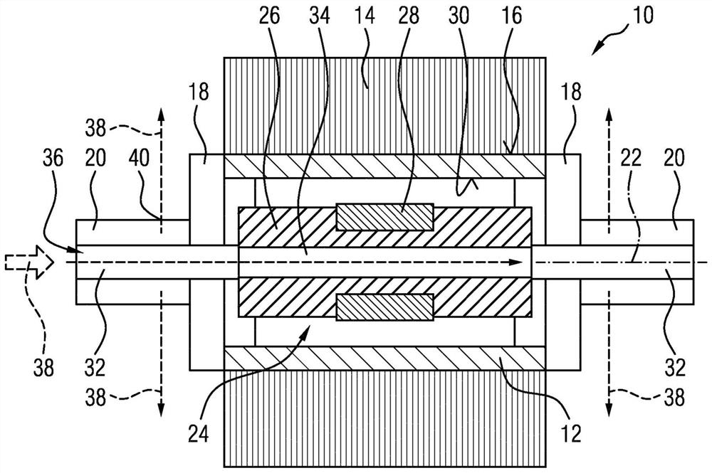
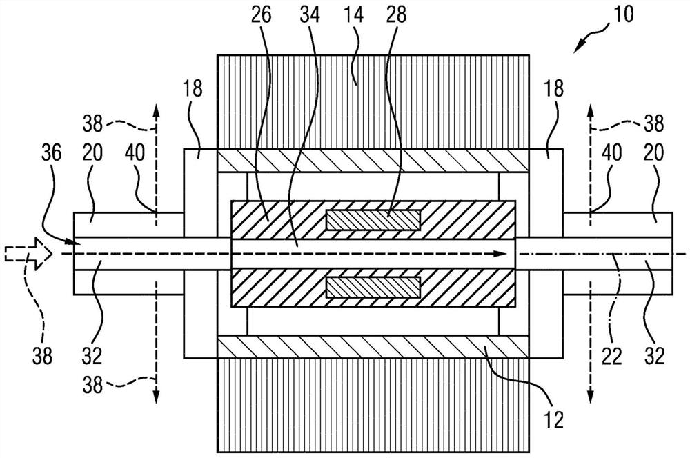
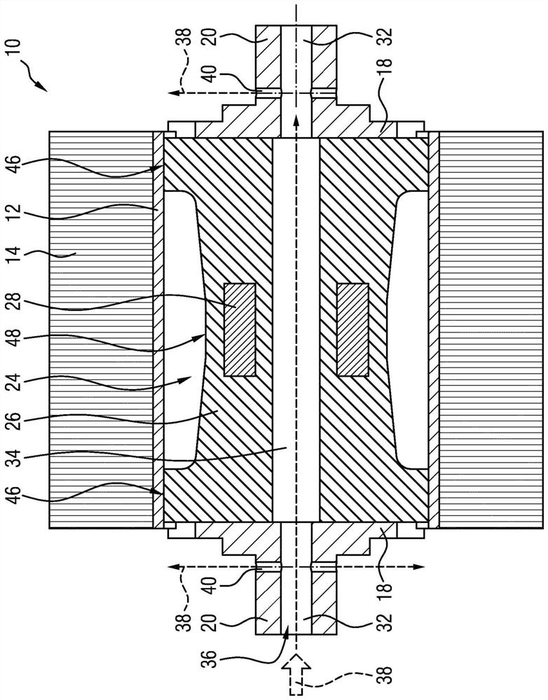
[0027] figure 1 The rotor 10 for the electric machine 11 is shown. The rotor 10 has a hollow-cylindrical laminated core carrier 12 . The laminated core carrier 12 can be, for example, a hollow rotor shaft. The laminated core support 12 preferably has an inner diameter of >30 mm. The rotor lamination core 14 is arranged on the lamination core support 12 . Preferably, the rotor lamination core 14 is rotationally fixedly attached to the lamination core support 12 . This means that the rotor lamination core 14 is at least partially supported on the peripheral surface 16 of the lamination core carrier 12 and / or is preferably connected to this peripheral surface by a friction fit and / or by a material bond. Thus, rotational movement and / or torque of the rotor lamination core 14 may be transmitted to the lamination core support 12 .

[0028] An end flange 18 is arranged at each axial end of the laminated core support 12 , wherein each end flange 18 has a journal 20 formed coaxial...


PUM


Abstract

The invention relates to a rotor (10) for arrangement in an electric machine (11), the rotor having a hollow-cylindrical laminated core support (12) on an outer peripheral surface (16) of the laminated core support A rotor lamination core (14) can be arranged, and at each axial end of the lamination core support (12) an end flange (18) is arranged, wherein each end flange (18) has A journal (20) and a shock absorber (24) is arranged and / or formed in the hollow cylindrical laminated core support (12).

Description

technical field [0001] The invention relates to a rotor for arrangement in an electric machine, wherein the rotor has an integrated vibration damper. The invention also relates to an electric machine with a rotor according to the invention, and a motor vehicle with an electric machine according to the invention. Background technique [0002] It is well known that electric machines have rotors. Known electric machines generally include a stator, and a rotor rotatable in the stator about an axis of rotation of the rotor. [0003] Furthermore, it is known that bending vibrations are continuously generated in the rotor shaft of the rotor during operation. The main reason for this could be the large change in the rotational speed of the shaft during acceleration and braking. However, rotor imbalance can also trigger bending vibrations. Therefore, rotors with dampers are also known, which are designed to avoid or reduce harmful torsional vibrations in the rotatable shaft of th...

Claims


Application Information

Patent Timeline
Patent Type & Authority Patents(China)
IPC IPC(8): H02K7/04H02K7/00H02K7/02H02K1/30H02K15/16F16F15/12F16F15/32H02K1/32H02K9/19
CPCH02K1/30H02K1/32H02K7/003H02K7/02H02K7/04H02K9/19H02K15/165F16F15/30F16F15/1442F16F15/13107Y02E60/16
Inventor H·弗勒利希
Owner VTESCO TECH GMBH
Learn More