
Miniaturization band elimination type frequency selective surface

A frequency-selective surface and band-stop technology, which is applied in waveguide devices, electrical components, circuits, etc., can solve the problems of high cost, complex design of frequency-selective surface unit structure, and difficult production, and achieve low cost and unit structure design. Easy, cell size reduction effect

Inactive Publication Date: 2014-09-24
NANJING NORMAL UNIVERSITY
View PDF5 Cites 14 Cited by
  • Summary
  • Abstract
  • Description
  • Claims
  • Application Information

AI Technical Summary

Problems solved by technology

In view of this, the current miniaturization technology of most frequency selective surfaces is mainly realized by using metal wires, gaps in meandering units or using external lumped capacitance and inductance elements; the design of the former frequency selective surface unit structure is very complicated, while the latter integrates The electrical parameters of the total components will be affected by ambient temperature, humidity and even strong electromagnetic fields; in addition, a so-called three-dimensional frequency selective surface has been proposed. This kind of three-dimensional frequency selective surface is mostly based on multi-layer dielectric substrates, which is difficult to manufacture , the cost is high; therefore, it is necessary to further design a new type of frequency selective surface miniaturized unit structure

Method used


Image

  • Miniaturization band elimination type frequency selective surface
  • Miniaturization band elimination type frequency selective surface
  • Miniaturization band elimination type frequency selective surface

Examples


Embodiment Construction

[0014] The embodiment of a miniaturized band-stop frequency selective surface provided by the present invention will be described in detail below in conjunction with the accompanying drawings:

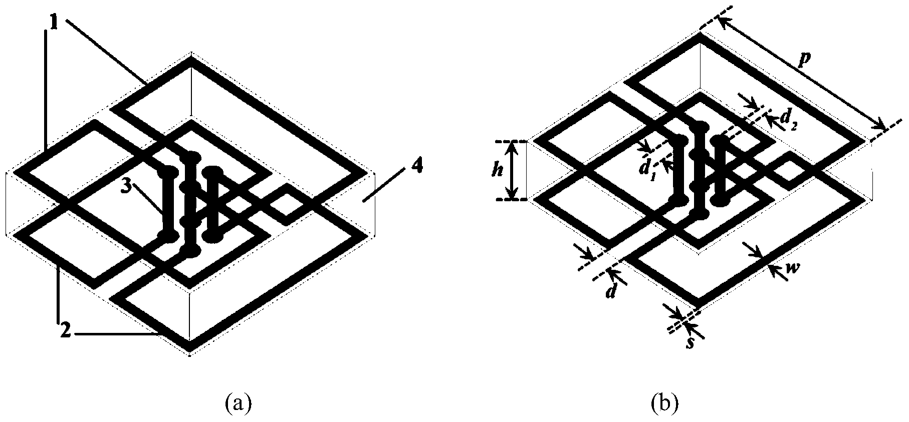
[0015] A unit of a miniaturized band-stop frequency selective surface designed by the present invention is as figure 1 As shown in (a), it includes a pair of rectangular open metal rings 1 on the upper surface of the dielectric substrate, a pair of rectangular open metal rings 2 on the lower surface of the dielectric substrate, and four metal through holes 3 connecting the opening ends of the rectangular metal rings on the upper and lower surfaces of the dielectric substrate. The opening directions of the rectangular metal rings are opposite, and the pair of rectangular metal rings on the lower surface are obtained by rotating the pair of rectangular metal rings on the upper surface by 90 degrees as a whole, and the metal thin wires of the four rectangular metal rings on the upper and l...


PUM


Abstract

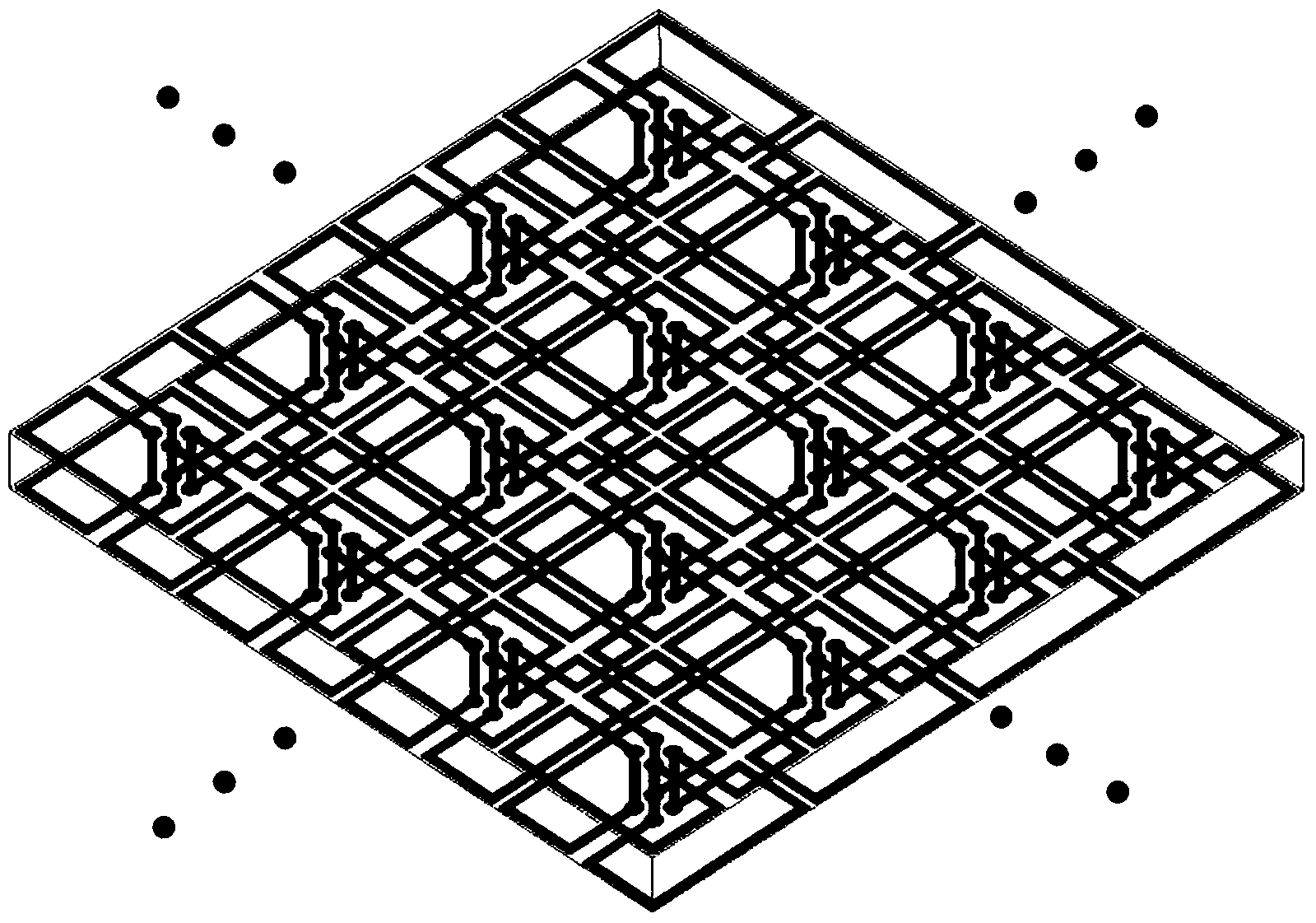
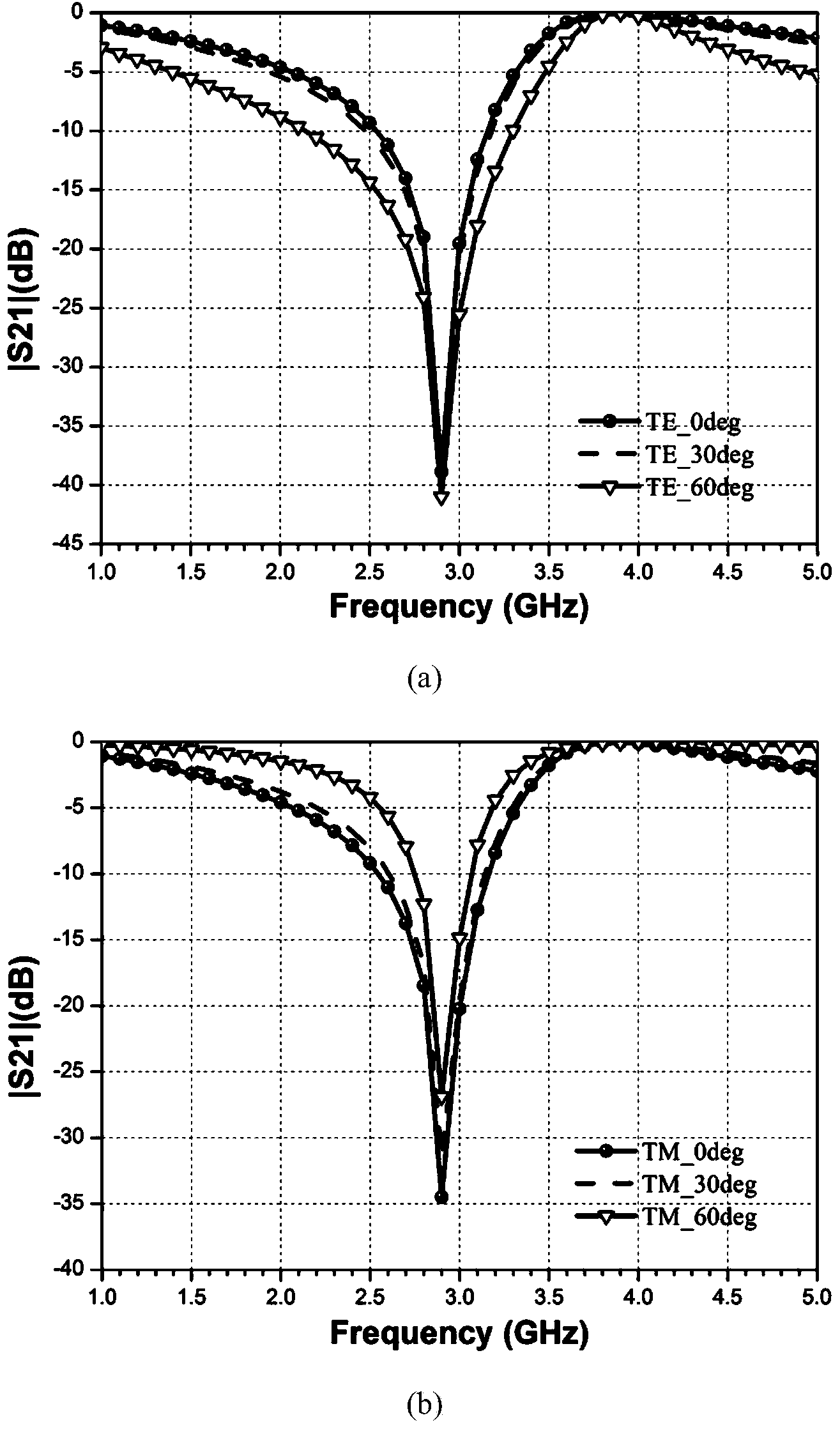
The invention discloses a miniaturization band elimination type frequency selective surface. The miniaturization band elimination type frequency selective surface is formed by periodically arranging a plurality of same unit structures on a dielectric substrate in the horizontal two-dimensional direction, and each unit structure comprises a pair of opened metal rings located on the upper surface of the dielectric substrate, a pair of opened metal rings located on the lower surface of the dielectric substrate and metal through holes; the opening directions of the two metal rings in each pair are opposite, the two pairs of opened metal rings on the upper surface and the lower surface are perpendicularly staggered in the electromagnetic wave incidence direction, and the four metal through holes symmetrically formed in each unit center are used for correspondingly connecting the opening ends of the four metal rings in an up and down mode. The frequency selective surface has the band elimination characteristic due to inductance and capacitance resonance provided by the unit structures, and propagation of electromagnetic waves within specific frequency bands can be blocked; meanwhile, the frequency selective surface further has the advantages of being stable in response to different-polarization and different-incidence-angle frequencies of the space electromagnetic waves and being miniaturized.

Description

technical field [0001] The invention belongs to the field of electromagnetic field and microwave technology. In particular, it relates to a band-stop type frequency selective surface with unit size miniaturization. Background technique [0002] Frequency Selective Surface (FSS) is a two-dimensional periodic structure composed of periodic arrangements of resonant units. Frequency selective surfaces have been widely studied and applied in military and civilian fields such as spatial filters, radomes, antenna reflectors, and absorbing materials. However, when the frequency selective surface is applied in the above fields, it faces a prominent problem, that is, when the frequency selective surface is used in a limited area, if the unit size of the frequency selective surface is relatively large, the number of units in the limited area will be relatively small , will affect the relative performance of the frequency selective surface, for example: the low sensitivity of the freq...

Claims


Application Information

Patent Timeline
IPC IPC(8): H01P1/20H01P1/203
Inventor 唐万春施永荣庄伟王橙刘升沈来伟黄承朱建平
Owner NANJING NORMAL UNIVERSITY
Learn More