Eureka AIR delivers breakthrough ideas for toughest innovation challenges, trusted by R&D personnel around the world.

Well-bore sulfur deposit visual experiment device and well-bore sulfur deposit visual experiment method

An experimental device, sulfur deposition technology, applied in the direction of analyzing materials, instruments, etc.

Active Publication Date: 2014-09-24
SOUTHWEST PETROLEUM UNIV
View PDF3 Cites 17 Cited by
  • Summary
  • Abstract
  • Description
  • Claims
  • Application Information

AI Technical Summary

Problems solved by technology

At present, there is no device that can realize the microscopic visualization experiment of wellbore sulfur deposition

Method used


Image

  • Well-bore sulfur deposit visual experiment device and well-bore sulfur deposit visual experiment method
  • Well-bore sulfur deposit visual experiment device and well-bore sulfur deposit visual experiment method
  • Well-bore sulfur deposit visual experiment device and well-bore sulfur deposit visual experiment method

Examples


Embodiment 1

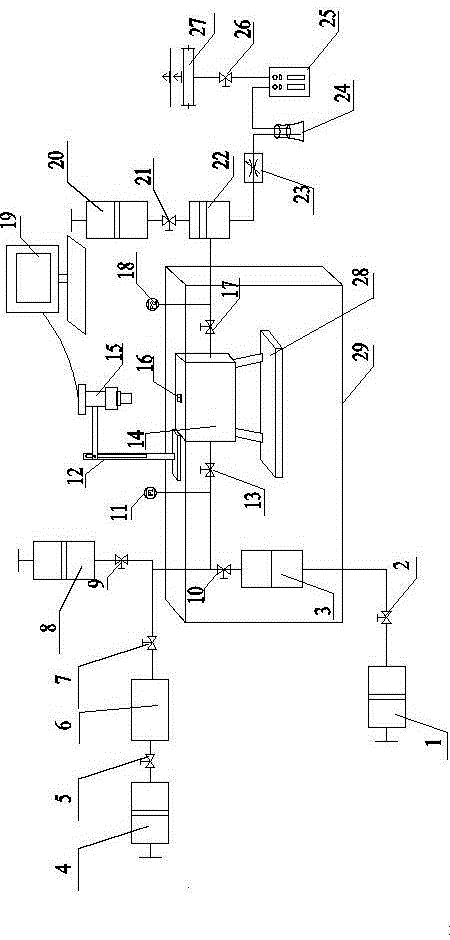
[0040] The microscopic visualization experiment method of wellbore sulfur deposition using the wellbore sulfur deposition visualization experiment device includes the following steps:

[0041] S1. Clean the intermediate container 3 and all its experimental pipelines with alcohol and petroleum ether;

[0042] S2. Because the temperature and pressure of the gas sample retrieved from the field have changed significantly compared with the formation conditions, the phase state of the gas sample has changed. It is necessary to re-match the sample in the sample dispenser 6 according to the original formation conditions. If necessary, inject a certain proportion of gas samples into the sample dispenser 6 according to the original formation conditions;

[0043] S3. Weigh 5g of elemental sulfur powder, put it into the intermediate container 3, and use the vacuum pump 8 to vacuum the intermediate container 3; then use the booster pump to pressurize the interior of the intermediate container 3; ...

Embodiment 2

[0052] The microscopic visualization experiment method of wellbore sulfur deposition using the wellbore sulfur deposition visualization experiment device includes the following steps:

[0053] S1. Clean the intermediate container 3 and all its experimental pipelines with alcohol and petroleum ether;

[0054] S2. Because the temperature and pressure of the gas sample retrieved from the field have changed significantly compared with the formation conditions, the phase state of the gas sample has changed. It is necessary to re-match the sample in the sample dispenser 6 according to the original formation conditions. If necessary, inject a certain proportion of gas samples into the sample dispenser 6 according to the original formation conditions;

[0055] S3. Weigh 5g of elemental sulfur powder, put it into the intermediate container 3, and use the vacuum pump 8 to vacuum the intermediate container 3; then use the booster pump to pressurize the interior of the intermediate container 3; ...


PUM


Abstract

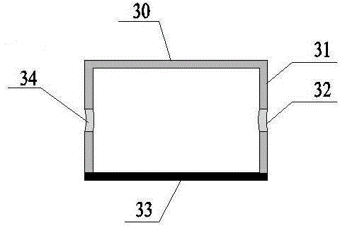
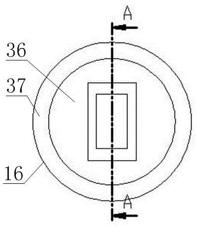
The invention discloses a well-bore sulfur deposit visual experiment device. The well-bore sulfur deposit visual experiment device comprises a displacement system, a well-bore sulfur deposit analog system, an image collecting system and a waste gas treating system, wherein the displacement system comprises a constant-speed constant-pressure pump (1), a middle container (3), a gas injection pump (4), a sampler (6), a vacuum pump (8), a back pressure pump (20), a back pressure valve (22) and a throttle valve (23); the well-bore deposit analogue system comprises a visual device (14), a visual window (16), a bracket (28) and a multifunctional oven (29); the image collecting system comprises a high-power microscope (15) and a computer (19). The invention further discloses an experiment method adopting the experiment device. The device and the method disclosed by the invention have beneficial effects of being capable of simulating well-bore production conditions, and realizing real-time observation of the whole microscopic dynamic process including an elemental sulfur separation way, elemental sulfur deposition, a crystal growth microscopic dynamic process, deposition morphology, and the like.

Description

technical field [0001] The invention relates to the technical field of oil and gas field exploitation, in particular to a visual experiment device and method for well bore sulfur deposition. Background technique [0002] High-sulfur gas reservoirs are widely distributed in the world. With the development of oil and gas fields in my country, more and more high-sulfur or ultra-high-sulfur gas fields have been discovered in my country. my country's sour gas reservoirs are mainly distributed in the Ordos Basin, Sichuan Basin, Bohai Bay Basin and Tarim Basin. High-sulfur gas reservoirs are a special type of gas reservoirs. In high-sulfur gas reservoirs, H 2 The existence of S makes its physical properties quite different from those of conventional natural gas. The biggest difference between high-sulfur gas reservoirs and conventional gas reservoirs is that in the process of gas well production, with the change of temperature and pressure, phases will occur. Change, elemental s...

Claims


Application Information

Patent Timeline
Patent Type & Authority Applications(China)
IPC IPC(8): G01N15/04
Inventor 刘建仪代建伟张广东李牧
Owner SOUTHWEST PETROLEUM UNIV
Why Eureka
Eureka Blog
Learn More