High-frequency automatic annealing method and device for screw hole of bearing ring

A technology for bearing rings and annealing devices, applied in furnaces, heat treatment equipment, heat treatment furnaces, etc., can solve the problems of unstable quality, high maintenance costs, complicated equipment structure and operation, etc., and achieve simple equipment structure and operation. The effect of low maintenance cost and low labor intensity of workers

Inactive Publication Date: 2017-08-25
FK BEARING GRP
View PDF9 Cites 0 Cited by
  • Summary
  • Abstract
  • Description
  • Claims
  • Application Information

AI Technical Summary

Problems solved by technology

[0002] For outer spherical bearings with bolt jackscrews, cracks are likely to occur around the threaded holes after the screws are installed, causing the bearings to loosen on the shaft, shortening the life of the bearings, causing equipment failures and complete machine breakdowns
Therefore, it is necessary to anneal the screw hole of the inner ring of the bearing. At present, the annealing equipment generally used in the industry is a high-frequency heating machine plus an induction coil. Workers wear gloves and hold the inner ring of the bearing vertically and place it under the induction coil. , the inner ring of the bearing is placed on the workbench, and its screw hole is located in the induction ring. After about 2 seconds, local induction heating is completed. This manual control and manual feeding, holding, and discharging method is labor-intensive and labor-intensive. Poor conditions, low production efficiency, and unstable quality affect the overall quality of the bearing
[0003] In view of this problem, the Chinese invention patent CN203174164U proposes an annealing device for the top wire hole of the inner ring of the outer spherical bearing with top wire. A vertical mandrel seat is arranged on the cooling table, and a heating ring is placed above the mandrel seat, imitating the above-mentioned artificial Induction annealing, but the degree of mechanization of this kind of device is low, it needs to manually load, discharge, start the heating device, and manually adjust the height of the bearing to align the screw hole with the induction coil, because the mandrel and the bearing ring are completely Contact, other parts of the bearing ring need to be cooled through the cooling table to maintain a suitable temperature of the workpiece, and the inlet and outlet pipes need to be set separately
Another Chinese invention patent application CN103740923A discloses a semi-automatic bearing high-frequency annealing device, which can automatically realize feeding, heating and discharging, but its structure is complicated, the manufacturing cost is high, and the machine maintenance cost is high. , Rotating device, lifting device, material return device and cooling device with cooling water pipes, three cylinders are required: push material cylinder, lift cylinder and material return cylinder, and the material is held and heated by the vertical mandrel clamp, and the bearing ring is easy to overheat , cooling is required, the operation of the machine is complicated, and the failure rate is high
[0004] Therefore, the high-frequency annealing method of the screw hole of the bearing inner ring of the existing equipment is to make the axis of the bearing ring in a vertical state, or use manual loading and unloading, with a low degree of mechanization, or use multiple cylinders Feeding, raising, and returning materials, and the fixture is heated by induction at the same time, which requires cooling and cooling. The structure and operation of the equipment are complex, the maintenance cost is high, and it is prone to failure

Method used


Image

  • High-frequency automatic annealing method and device for screw hole of bearing ring
  • High-frequency automatic annealing method and device for screw hole of bearing ring
  • High-frequency automatic annealing method and device for screw hole of bearing ring

Examples


Embodiment Construction

[0025] Preferred embodiments of the present invention will be described in detail below in conjunction with the accompanying drawings.

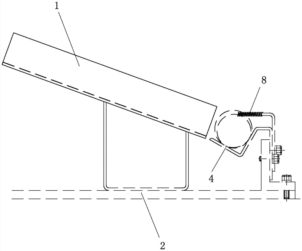
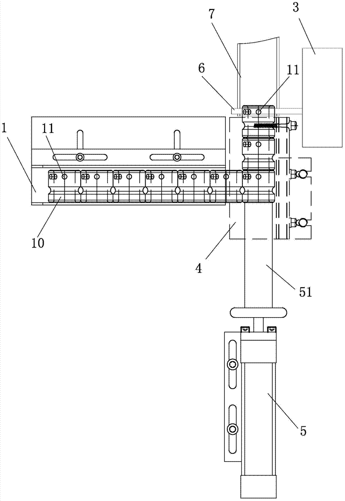
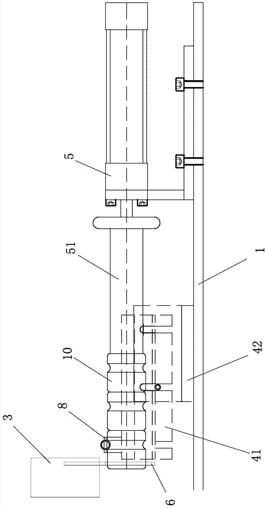
[0026] Such as Figure 1 to Figure 3 As shown, a high-frequency automatic annealing device for bearing ring screw holes includes a feeding chute 1, a feeding device, an induction fixture, a high-frequency heating machine 3, and an induction coil connected to the high-frequency heating machine 3. The feeding chute 1 is an inclined chute from high to low. The feeding chute 1 is fixed on the worktable 2 through the pillars. The angle between the feeding chute 1 and the workbench 2 is 15°-25°. The lower end of the feeding chute 1 is connected to the feeding induction fixture 4 connected vertically.

[0027] The feeding device includes a feeding cylinder and a feeding induction fixture 4. The feeding induction fixture 4 is used as a feeding trough and also as an induction fixture. The material receiving position of the feeding induction fixture 4...


PUM


Abstract

The invention provides a high-frequency automatic annealing method and device for the screw hole of a bearing ring. The feeding induction fixture of the annealing device is loaded with the material bearing position of the bearing ring and intersects the feeding groove vertically. , the axis of the bearing ring is horizontal and in line contact with the fixture; the feed induction fixture is an open structure that at least exposes the upper part of the bearing ring, the front and rear ends of the feed induction fixture are open, and the rear opening is provided with a The push rod connected to the feeding cylinder, the axis of the feeding cylinder is parallel to the length direction of the material receiving position, the feeding cylinder pushes the bearing ring to travel intermittently in the feeding induction fixture, and the induction coil is suspended in the feeding position. The outside of the front end of the material induction fixture, the ring surface of the induction coil is perpendicular to the length direction of the material receiving position. The invention can automatically realize feeding, heating and returning materials, has low labor intensity of workers, high production efficiency, effectively guarantees annealing quality, simple equipment structure and operation, and low manufacturing and maintenance costs.

Description

technical field [0001] The invention relates to the technical field of bearing production, in particular to a high-frequency automatic annealing method and device for screw holes of bearing rings. Background technique [0002] For outer spherical bearings with bolt top screws, cracks are likely to occur around the threaded holes after the screws are installed, causing the bearings to be loosened on the shaft, shortening the life of the bearings, causing equipment failures and complete machine paralysis. Therefore, it is necessary to anneal the screw hole of the inner ring of the bearing. At present, the annealing equipment generally used in the industry is a high-frequency heating machine plus an induction coil. Workers wear gloves and hold the inner ring of the bearing vertically and place it under the induction coil. , the inner ring of the bearing is placed on the workbench, and its screw hole is located in the induction ring. After about 2 seconds, local induction heatin...

Claims


Application Information

Patent Timeline
Patent Type & Authority Patents(China)
IPC IPC(8): C21D9/40C21D1/26
Inventor 施天津黄志东洪达毅
Owner FK BEARING GRP
Why Eureka
Try Eureka