
Full-automatic paint spraying assembly line

An automatic paint spraying machine and assembly line technology, which is applied in spray booths, spraying devices, coatings, etc., can solve the problems of low independent work efficiency of multiple devices, asynchronous work of multiple devices, and increased cleaning steps. The effect of labor cost, efficiency improvement, and time saving of mold washing

Inactive Publication Date: 2014-09-24
东莞市贾氏机械制造有限公司
View PDF9 Cites 30 Cited by
  • Summary
  • Abstract
  • Description
  • Claims
  • Application Information

AI Technical Summary

Problems solved by technology

However, in order to realize the spraying process of a complex material, usually multiple processes are required, and each process must include at least two steps of painting and drying, and it is also necessary to add a step of regularly cleaning the mold
Therefore, the traditional technology still has the following defects: 1) Multiple devices work independently, which not only takes up a lot of space, but also requires at least one person to operate each device, which costs more; 2) Multiple devices work out of sync, and each process There will be discontinuities in the interval, which needs to be transferred frequently, which will affect the work efficiency; 3) There will be paint leakage during the transfer process between the various processes, causing environmental pollution; 4) The independent work efficiency of multiple equipment is low, and the spraying of multiple parts cannot be completed at the same time

Method used


Image

  • Full-automatic paint spraying assembly line
  • Full-automatic paint spraying assembly line
  • Full-automatic paint spraying assembly line

Examples


Embodiment Construction

[0037] The present invention will be further described in detail below in conjunction with the accompanying drawings and specific embodiments.

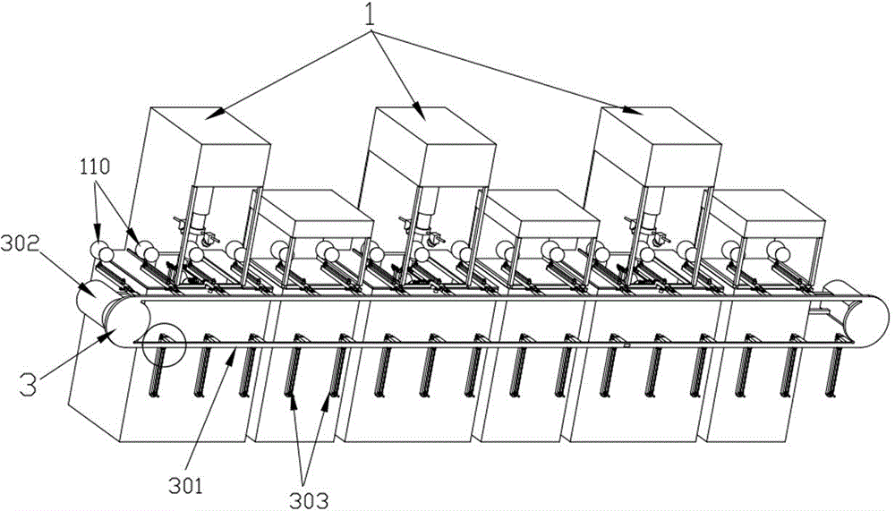
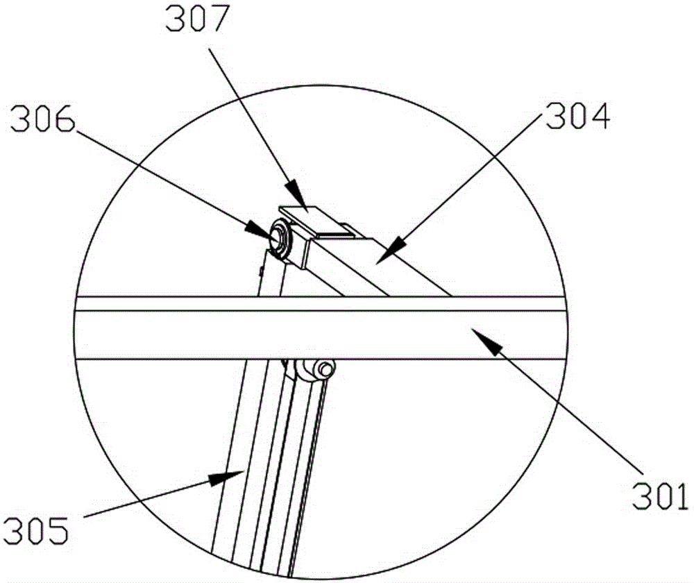
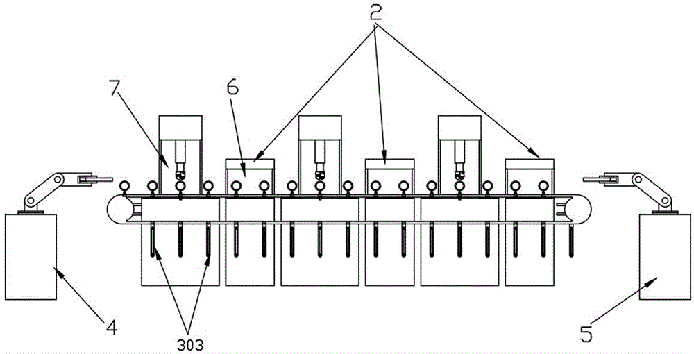
[0038] In this embodiment, refer to Figure 1 to Figure 6 , its specific embodiment includes an automatic paint spraying machine 1, an automatic dryer 2, an automatic assembly line 3, a feeding manipulator 4, an unloading manipulator 5 and a touch screen control platform for intelligently controlling the work of the assembly line.

[0039] Wherein, the automatic paint spraying machine 1 in the present embodiment is provided with three altogether, and the automatic dryer 2 corresponding to its quantity also is provided with three, is respectively positioned at the right side of each automatic paint spraying machine 1, makes automatic paint spraying machine 1 and automatic The dryers 2 are neatly arranged in a straight line. In order to ensure that the next process can be sprayed normally, fast drying is required after each spraying pro...


PUM


Abstract

The invention discloses a full-automatic paint spraying assembly line of the technical field of automatic machinery. The full-automatic paint spraying assembly line comprises automatic sprayers, automatic dryers, an automatic assembly line, a feeding mechanical hand, an unloading mechanical hand and a touch screen control platform, wherein more than two automatic sprayers are arranged, and a die cleaning mechanism, a spray operating room and a spray mechanism capable of moving triaxially are respectively mounted at the bottom, at the middle and at the top of each automatic sprayer; a die cleaning room used for storing die cleaning water is arranged at the bottom of each die cleaning mechanism; each die cleaning mechanism is composed of two die assembly components which have the same structure and are respectively arranged at the top and at the bottom of each die cleaning mechanism, more than two telescopic air cylinders used for connecting the two die assembly components, and an overturn component used for overturning the two die assembly components, so as to switch positions of the two die assembly components. The assembly line type paint spraying is highly efficient in that various paint spraying procedures can be implemented simultaneously along with synchronous paint drying, the paint with various colors can be sprayed at the same time, and various areas can be simultaneously coated, so that space and cost can be saved, the efficiency is improved, and time consumed for cleaning dies is shortened.

Description

technical field [0001] The invention relates to the technical field of automatic mechanical equipment, in particular to a fully automatic painting assembly line. Background technique [0002] Die injection and painting is a relatively labor-intensive link in the oil injection industry. Die injection usually has problems such as complex shapes and various types. The oil injection process is repetitive work, and there are problems such as frequent cleaning of the board. At the same time, after the painting is completed, it needs to be dried independently. Traditional manual fuel injection requires a lot of manpower, heavy workload, high labor intensity and will have a certain impact on the health of workers. [0003] For this reason, with the development of automation technology, there are automatic paint spraying machines and automatic dryers on the market, as well as semi-automatic mold washing equipment for mold washing. However, in order to realize the spraying process o...

Claims


Application Information

Patent Timeline
Patent Type & Authority Applications(China)
IPC IPC(8): B05B15/12B05B13/00B05B13/02
CPCB05B13/0221B05B13/0421B05B16/20B05B16/40
Inventor 贾锦育
Owner 东莞市贾氏机械制造有限公司
Learn More