
A kind of magnetic resonance imaging equipment and magnetic resonance scanning method

A magnetic resonance imaging and equipment technology, applied in medical science, diagnosis, diagnostic recording/measurement, etc., can solve the problems of signal-to-noise ratio drop, size limitation, long time for placing patients and placing local coils, etc., to reduce work Quantity, the effect of improving the efficiency of use

Active Publication Date: 2019-04-26
SHENZHEN UNITED IMAGING HEALTHCARE CO LTD
View PDF8 Cites 0 Cited by
  • Summary
  • Abstract
  • Description
  • Claims
  • Application Information

AI Technical Summary

Problems solved by technology

[0005] When performing MRI whole body scanning, the local coils on the back of the patient are generally arranged first, usually the spine coil 102, and then the patient is placed on the hospital bed 47, the head coil 101 is closed, and then various local coils are covered on the patient to achieve Full-body coverage: Generally, the upper body uses the abdominal coil 103. Due to the size limitation of the coil, two abdominal coils 103 are used for adult scanning; for the legs, the lower limb coil 104 is generally preferred. The local coil procedure usually takes 10-15 minutes
[0006] The disadvantage of this whole-body scanning method is that the doctor needs to place and arrange these local coils manually, and it takes a long time to place the patient and place the local coils, which makes the use efficiency of the magnetic resonance system too low; overlap, which will cause magnetic coupling between the coils, thereby reducing the signal-to-noise ratio of the
[0008] Therefore, it is necessary to propose a new technical solution, which can reduce the time for placing the patient and placing the local coil, improve the efficiency of the MRI system, reduce the workload of the doctor, and avoid the signal loss caused by the magnetic coupling caused by the partial overlap of the abdominal coil. Noise Ratio Decrease

Method used


Image

  • A kind of magnetic resonance imaging equipment and magnetic resonance scanning method
  • A kind of magnetic resonance imaging equipment and magnetic resonance scanning method
  • A kind of magnetic resonance imaging equipment and magnetic resonance scanning method

Examples


Embodiment Construction

[0044] In order to make the above objects, features and advantages of the present invention more comprehensible, specific implementations of the present invention will be described in detail below in conjunction with the accompanying drawings.

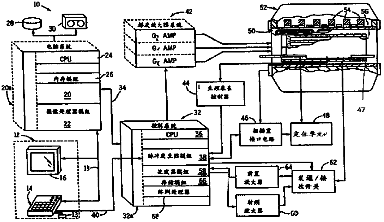
[0045] figure 2 The main components of a magnetic resonance system 10 incorporating the present invention are shown, the system being controlled via an operator console 12 including a keyboard and / or other input device 13 , a control panel 14 and a display screen 16 . Console 12 is connected via connection 18 to a separate computer system 20 which enables an operator to control the generation and display of images on display screen 16 . The computer system 20 includes a number of modules communicating with each other through the backplane 20a, these modules include an image processor module 22, a CPU module 24 and a memory module 26, the memory module 26 can be a well-known in the industry for A framebuffer that stores groups of imag...


PUM


Abstract

The invention provides magnetic resonance imaging equipment and a magnetic resonance scanning method. Before the magnetic resonance imaging equipment carries out magnetic resonance body scan, each local coil does not need to be manually placed. During scanning, a movable coil device (3) and a fixed coil device (102) are directly used to automatically be close to or fit the current part needing to be scanned to receive radio-frequency signals, the time for placing a patient and the coils before magnetic resonance body scan can be saved, and the using efficiency of a magnetic resonance system is improved. The coils are automatically placed, so that the workload of doctors can be reduced. As the local coils do not have splicing application when the upper body of the patient is scanned, the problem that the signal to noise ratio is decreased due to magnetic coupling among the coils is solved.

Description

【Technical field】 [0001] The present invention relates to the technical field of magnetic resonance imaging (MRI, Magnetic Resonance Imaging), in particular to a magnetic resonance imaging device and a magnetic resonance scanning method. 【Background technique】 [0002] The basic principle of magnetic resonance imaging is: some atoms containing a single number of protons in human tissue, such as hydrogen atoms, can spin and generate magnetic moments, which can be regarded as some small magnets. Under normal conditions, the spin direction of these small magnets The arrangement is irregular, but under the action of a fixed main magnetic field, there will be a directional arrangement; at this time, when a radio frequency pulse with the same frequency as the main magnetic field is applied, these hydrogen atoms absorb a certain amount of energy and resonate, and the spin direction is under the action of the radio frequency pulse The deflection occurs and the arrangement is regular...

Claims


Application Information

Patent Timeline
Patent Type & Authority Patents(China)
IPC IPC(8): A61B5/055
Inventor 张强
Owner SHENZHEN UNITED IMAGING HEALTHCARE CO LTD
Learn More