Electromagnetic force hub motor

A wheel hub motor and electromagnetic force technology, which is applied to motors, synchronous motors with stationary armatures and rotating magnets, electric vehicles, etc., can solve the problem of increasing the unsprung mass and wheel inertia, limited electric braking performance, and electric Small braking capacity and other issues, to achieve the effect of light weight, low mechanical wear and simple structure

Active Publication Date: 2014-09-17
四川金色映像文化传播有限公司
View PDF6 Cites 0 Cited by
  • Summary
  • Abstract
  • Description
  • Claims
  • Application Information

AI Technical Summary

Problems solved by technology

[0005] Disadvantage 1: Increase the moment of inertia of the unsprung mass and the hub, which affects the handling of the vehicle
[0006] Disadvantage 2: The performance of electric braking is limited, and it takes a lot of power to maintain the operation of the braking system
Due to the relationship between energy sources, electric braking is also the first choice for electric vehicles. However, for vehicles driven by in-wheel motors, due to the small electric braking capacity of the in-wheel motor system, it cannot meet the requirements of the braking performance of the whole vehicle, and additional mechanical brakes are required. However, for ordinary electric passenger cars, without the vacuum pump driven by the traditional internal combustion engine, an electric vacuum pump is needed to provide brake boost, but it also means greater energy consumption, even if regenerative braking can recover some energy, If the effectiveness of the braking system is to be ensured, the energy consumed by the braking system is also one of the important factors affecting the cruising range of electric vehicles

Method used


Image

  • Electromagnetic force hub motor
  • Electromagnetic force hub motor

Examples


Embodiment Construction

[0019] The technical solutions in the embodiments of the present invention are clearly and completely described below in conjunction with the accompanying drawings in the embodiments of the present invention. Obviously, the described embodiments are only part of the embodiments of the present invention, not all of them. Based on the embodiments of the present invention, all other embodiments obtained by persons of ordinary skill in the art without making creative efforts belong to the protection scope of the present invention.

[0020] In the following description, a lot of specific details are set forth in order to fully understand the present invention, but the present invention can also be implemented in other ways different from those described here, and those skilled in the art can do it without departing from the meaning of the present invention. By analogy, the present invention is therefore not limited to the specific examples disclosed below.

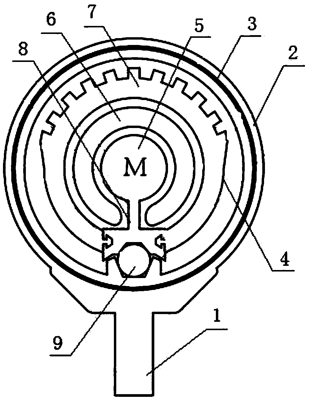
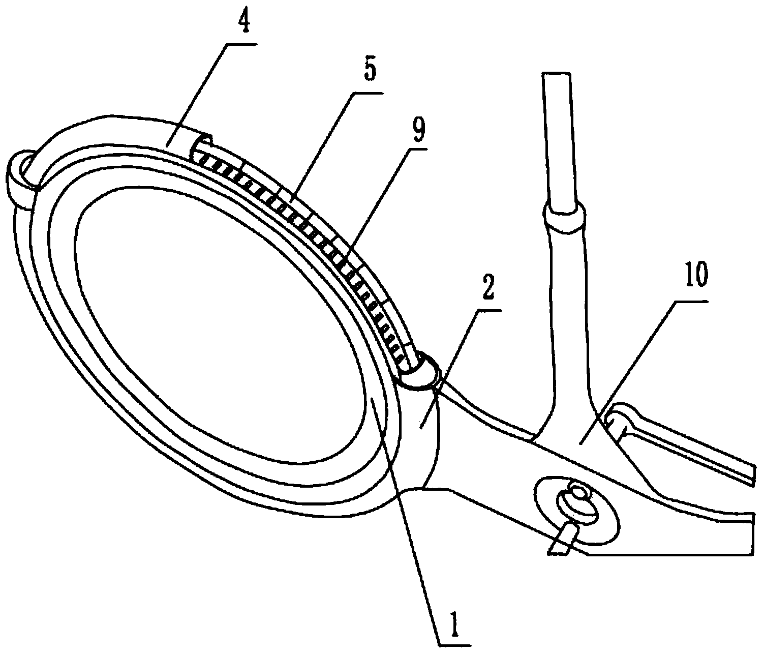
[0021] Such as Figure...


PUM


Abstract

The invention discloses an electromagnetic force hub motor and relates to the technical field of magnets which rotate around an armature. The electromagnetic force hub motor comprises a hub stator. An arc fixing sleeve is arranged on part of the outer periphery of the hub stator. A coil is arranged on the arc fixing sleeve. A circular rotor component is arranged on the periphery of the hub stator. A plurality of permanent magnets are arranged on the circular rotor component in the periphery direction. The rotor component is matched with the periphery of the hub stator in a rolling mode. The hub stator is fixedly arranged. The arc fixing sleeve is fixed relative to the position of the hub stator. A part of the circular rotor component penetrates through the coil on the arc fixing sleeve, and when the coil is electrified, the circular rotor component moves in a circling mode with the circle center of the hub stator as the circle center under the effect of outer force. According to the electromagnetic force hub motor, electromagnetic transmission and control principles are used, a mechanical structure is greatly simplified, obvious advantages of low abrasion, high efficiency, light weight, flexible control, low fault rate and the like are achieved, and wide application and promotion prospect is achieved.

Description

technical field [0001] The invention relates to the technical field of magnets rotating around an armature, in particular to an electromagnetic force hub motor that is easy to use and sensitive to control. Background technique [0002] In-wheel motor technology, also known as in-wheel motor technology, is characterized by the integration of power, transmission and braking devices into the wheel hub, thus greatly simplifying the mechanical parts of electric vehicles. Wheel hub motor technology is not new. As early as 1900, Porsche first produced electric vehicles with front wheels equipped with hub motors. In the 1970s, this technology was applied in fields such as mine transport vehicles. As for the in-wheel motors used in passenger cars, Japanese manufacturers have developed this technology earlier and are currently in a leading position. International auto giants including GM and Toyota have also been involved in this technology. At present, domestic self-owned brand auto...

Claims


Application Information

Patent Timeline
Patent Type & Authority Applications(China)
IPC IPC(8): H02K21/24
CPCY02T10/641Y02T10/64
Inventor 王飞
Owner 四川金色映像文化传播有限公司
Why Eureka
Try Eureka