A connecting and folding belt correcting and bending mechanism

A technology of bending mechanism and shape correction, which is applied in the field of cold stamping and bending, can solve the problems of increasing mold manufacturing cost and maintenance cost, complicated bending process, and unguaranteed accuracy, so as to improve bending work efficiency and save replacement Mold time and the effect of shortening the time for mold replacement

Active Publication Date: 2017-01-25
ANHUI XINYUE PRECISION MACHINERY
View PDF6 Cites 0 Cited by
  • Summary
  • Abstract
  • Description
  • Claims
  • Application Information

AI Technical Summary

Problems solved by technology

[0009] For bending from 45 degrees to 90 degrees, place the workpiece 8' bent at 45 degrees between the binder plate 3'' and the bending plate 7'' of the lower die, and the bending part 7' of the lower die 'The surface matched with the stamping surface 101'' of the bending punch 1'' is a vertical surface, thereby obtaining a 90-degree workpiece 8'' to be bent. When this process is completed, the workpiece 8'' to be bent is obtained as 90 degrees, but the accuracy cannot be guaranteed within ±0.1
This process requires three steps, and each process step requires the use of different bending and shape-correcting mechanisms. The bending process is complicated and the processing cycle is long, which undoubtedly increases the manufacturing cost and maintenance cost of the mold, and the productivity is not high.

Method used


Image

  • A connecting and folding belt correcting and bending mechanism
  • A connecting and folding belt correcting and bending mechanism
  • A connecting and folding belt correcting and bending mechanism

Examples


Embodiment 1

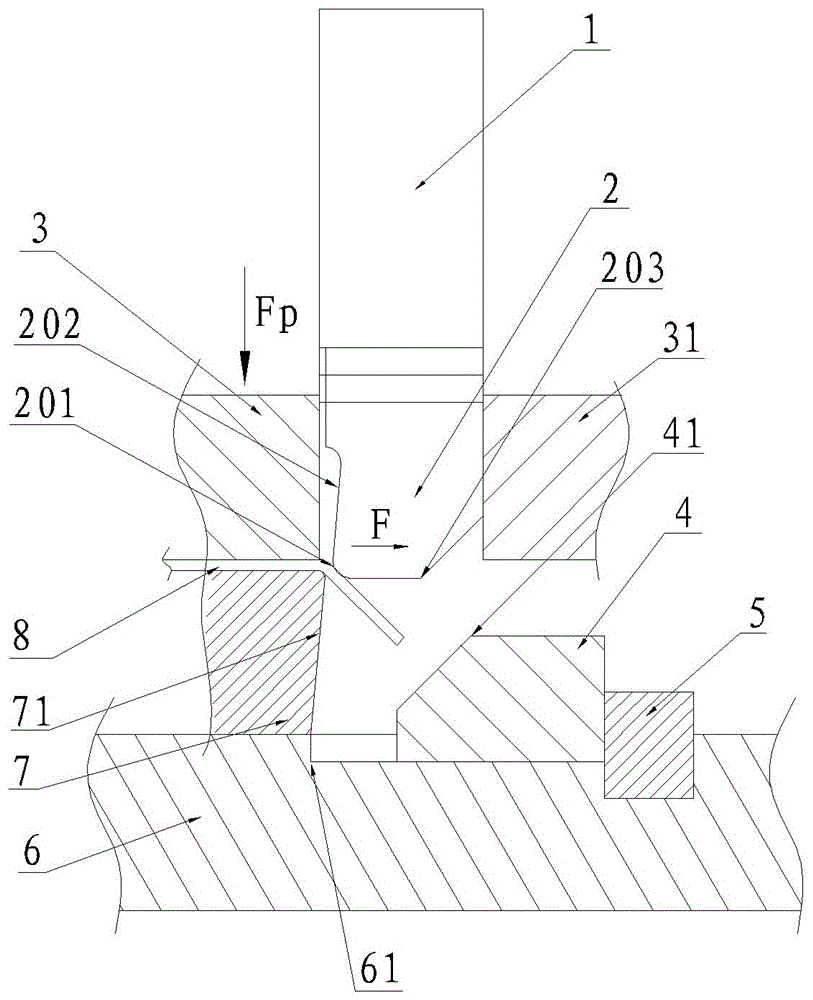
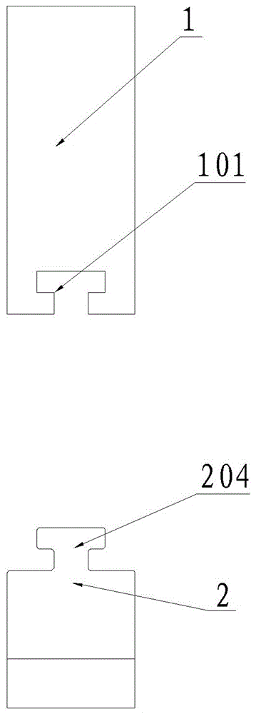
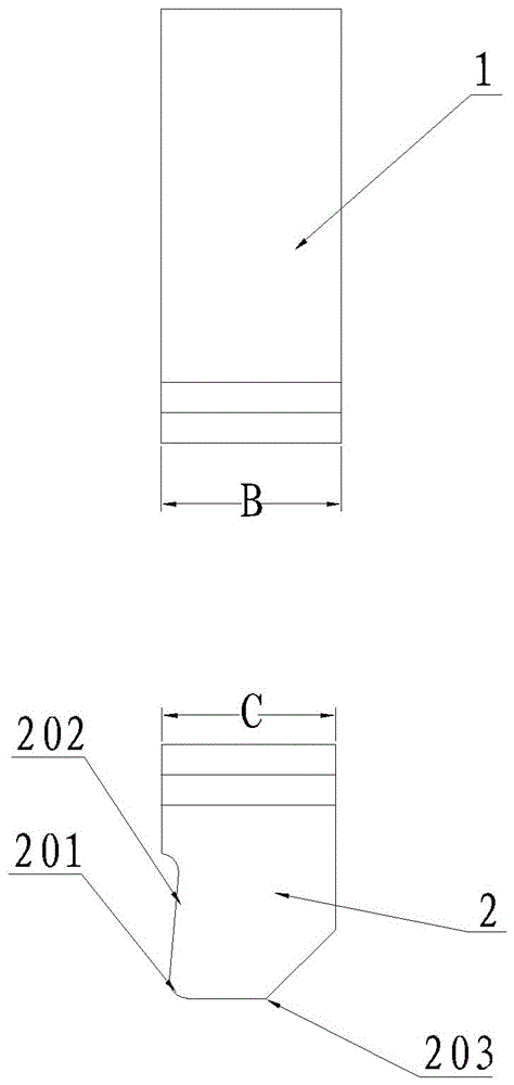
[0042] like figure 1 , Figure 4 and Figure 5 As shown in , it is a schematic diagram of the cold stamping process of a simple part using a set of fixed bending punches and movable bending punches, where figure 1 for figure 1 It is the state when the movable bending punch of an embodiment of the present invention has just touched the product. At this time, the movable bending punch 2 is under the action of the friction force F with the workpiece 8 to be processed along the 45 When the fixed bending punch 1 touches the 45-degree inclined surface of the workpiece 8 to be processed, the fixed bending punch 1 starts to stamp the workpiece 8 to 90-degree bending state; Figure 4 It is a schematic diagram of the structure of the movable bending punch of an embodiment of the present invention, where the weight of the movable bending punch becomes Fa. At this time, the 90-degree bending ends, and the 90-degree shape correction begins to prepare; Figure 5 It is a bending state...

Embodiment 2

[0045] In order to satisfy as Figure 10 For the part to be bent with two ears shown, a pair of through holes 9 are opened on the ears 10 of the part to be bent with two ears. The design requires that the coaxiality of the pair of through holes 9 on the two ears should not be greater than 0.2, and the material is SPFH540 , thickness T=2.0, need mass production.

[0046] Process analysis: The material has large springback, and it is difficult to bend with corners. The opening size requires 8+0.2, the tolerance is small, and the stability of the bending angle is the key factor affecting the coaxial 0.2 of the two holes on the side.

[0047] Process plan: continuous mold, two steps of bending, the first step adopts the existing technology to bend 45 degrees, and the second step uses the continuous folding belt shaping and bending mechanism of the present invention, such as Figure 11 Shown is a schematic diagram of the continuous folding belt shaping structure of the double-eare...


PUM

PropertyMeasurementUnit
thicknessaaaaaaaaaa

Abstract

The invention discloses a continuously bent belt correction bending mechanism, comprising a fixed bend punch, a movable bend punch and a tapered wedge guide block, wherein the movable bend punch is connected below the fixed bend punch, and the movable bend punch and the fixed bend punch are of a movable structure for overlapping bend punches in the second bending process and the third bending process; positions, corresponding to the fixed bend punch and the movable bend punch, of a swaging plate are provided with through holes, the overlapped movable bend punch and fixed bend punch penetrates through the through holes in the middle of the swaging plate; the tapered wedge guide block is connected to one side of a lower die seat bending block and is provided with a guide block inclined surface, the movable bend punch is provided with a punch inclined surface, and the guide block inclined surface and the punch inclined surface are matched for use, so that the existing second bending process and the existing third bending process are effectively combined into one process, the time of replacing dies in the bending process is saved, and the manufacturing cost and the maintenance cost of a set of die are also reduced.

Description

technical field [0001] The invention relates to the technical field of cold stamping and bending, in particular to a shape-correcting and bending mechanism for continuous folding belts. Background technique [0002] In the field of cold stamping, there is often a bending process. When the bending angle tolerance is small and the material springback is large, it is often necessary to add a shaping process after bending to correct the angle and press to ensure the stability of the angle. [0003] the following Image 6 As a bending example, the material to be bent is S550MC, the thickness T is 3.0cm, and the bending angle is 90.0±0.1. [0004] First analyze the process: the material is S550MC, T=3.0, this material is very elastic, but its angle requirements are high, and the tolerance is only ±0.1. Angles are difficult to control. Multi-step bending and shaping are required to ensure the controllability and stability of its angle. [0005] At the current level of bending te...

Claims


Application Information

Patent Timeline
Patent Type & Authority Patents(China)
IPC IPC(8): B21D21/00B21D37/10
Inventor 王一新杨朔冰刘明
Owner ANHUI XINYUE PRECISION MACHINERY
Why Eureka
Try Eureka