Metal element deformation-detecting device
A state detection device, a technology of metal components, applied in the direction of measuring devices, testing of mechanical components, testing of machine/structural components, etc., can solve problems such as low transmission efficiency and wear of pulleys, and achieve the effect of improving detection accuracy
- Summary
- Abstract
- Description
- Claims
- Application Information
AI Technical Summary
Problems solved by technology
Method used
Image

Examples
no. 1 Embodiment approach
[0051] First, according to Figure 1 to Figure 5 A first embodiment of the present invention will be described.
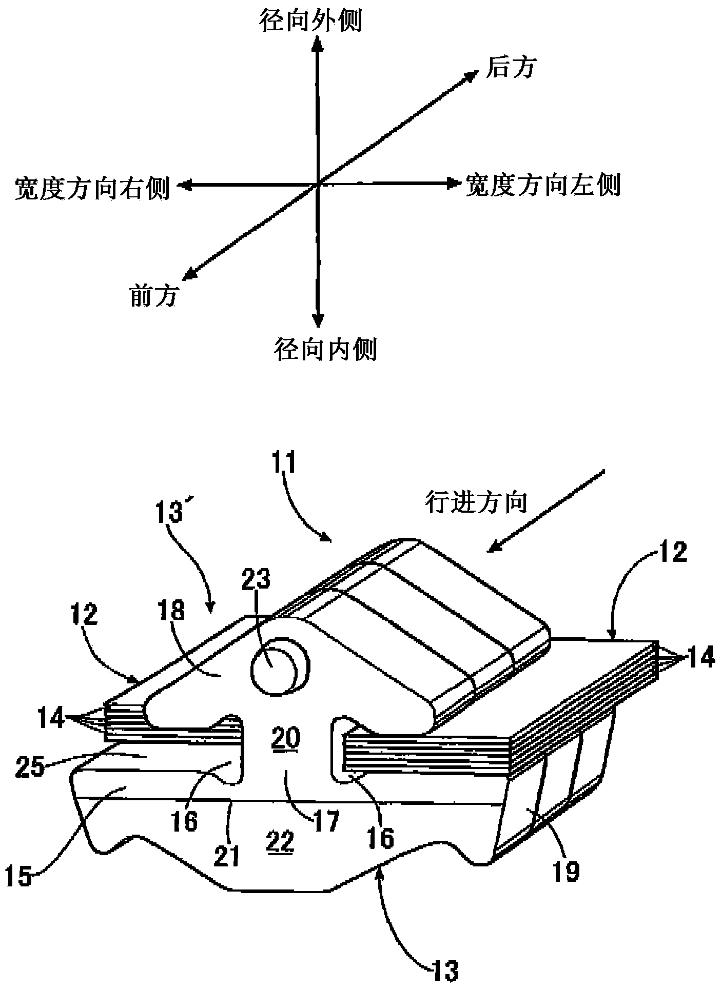
[0052] In addition, the definitions of the radial direction, width direction, and front-rear direction of metal elements used in this specification are as follows figure 1 shown. The radial direction is defined as the radial direction of the pulley in contact with the metal element, the side closer to the axis of the pulley is the radial inner side, and the side farther from the axis of the pulley is the radial outer side. In addition, the width direction is defined as the direction along the shaft of the pulley which abuts on the metal member, and the front-rear direction is defined as the direction along the moving direction of the metal member.
[0053] Such as figure 1 As shown, a metal belt 11 used in a belt-type continuously variable transmission is supported by a pair of left and right metal ring assemblies 12, 12, and a plurality of metal elements 13... ...
no. 2 Embodiment approach
[0063] Next, according to Figure 6 and Figure 7 A second embodiment of the present invention will be described.
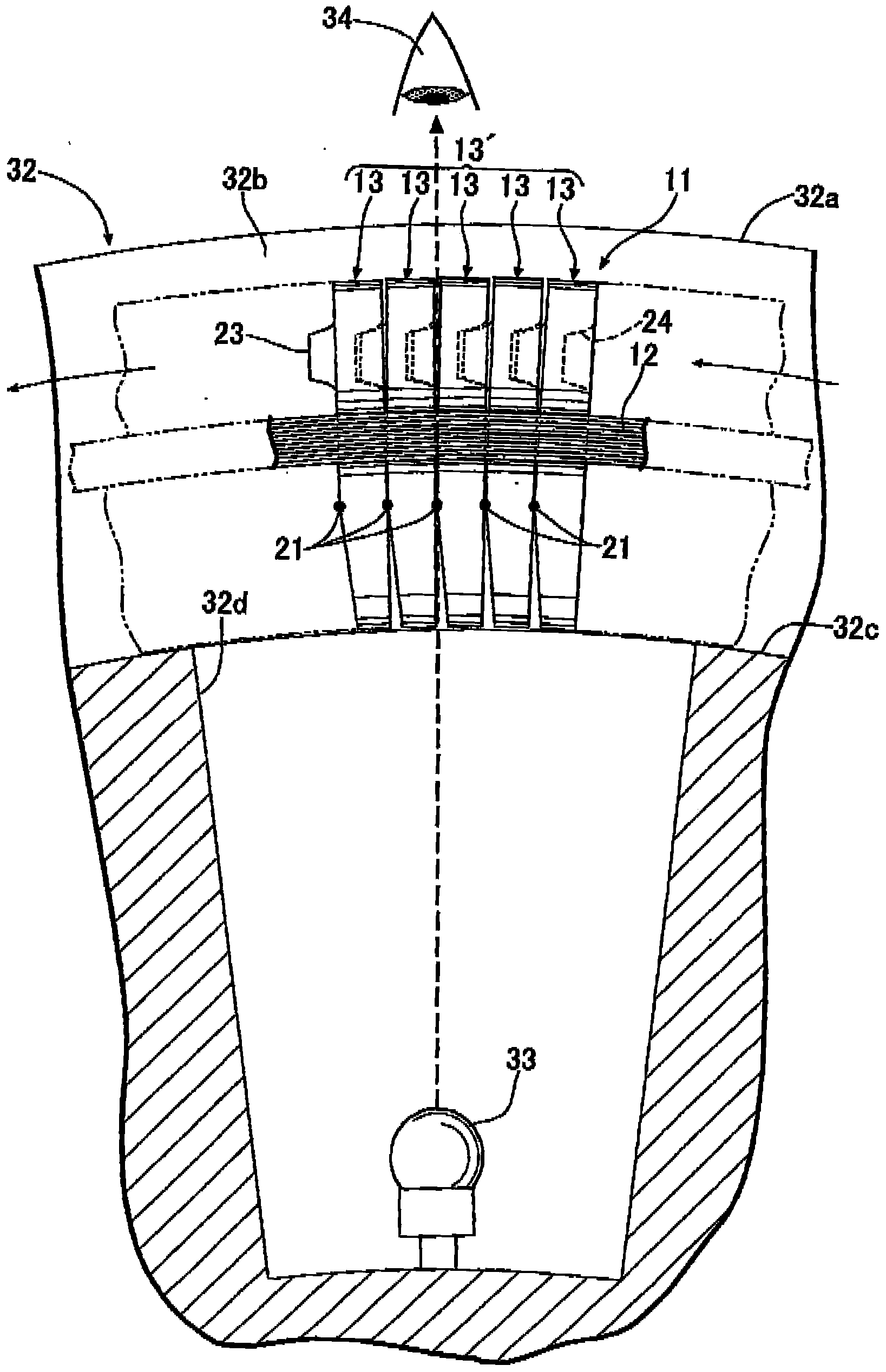
[0064] Such as figure 2 As shown, in the first embodiment, the light leaked from the gap between the metal elements 13... is visually observed, but as Figure 6 As shown, in the second embodiment, the light leaked from the gap between the metal elements 13... is observed by imaging with an imaging means 35 such as a CCD camera, for example.
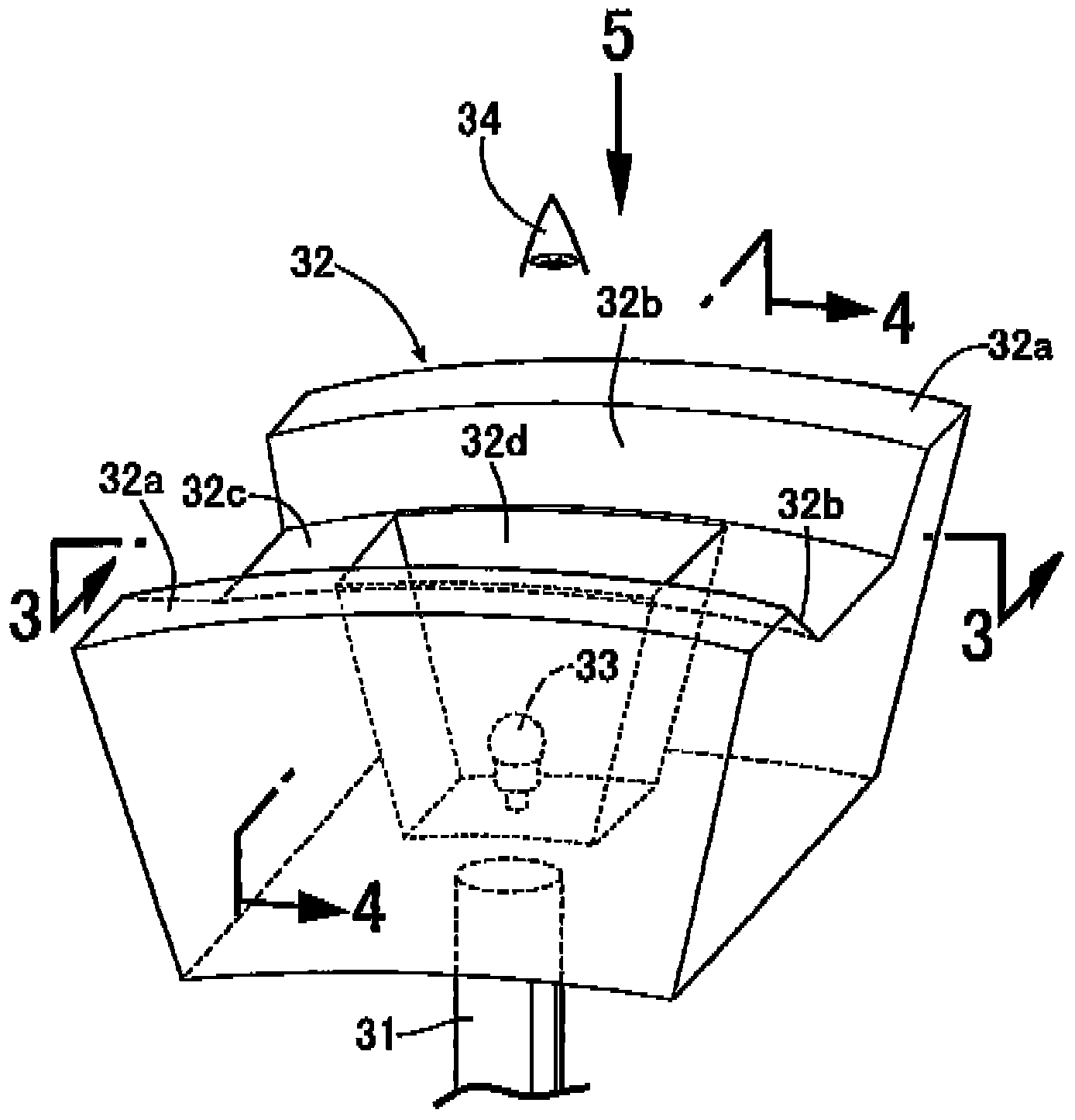
[0065] The dummy pulley 32 of the second embodiment has the same circular shape as an actual pulley, and the dummy pulley 32 is rotatably supported by a rotating shaft 37 vertically fixed to the stay 31 . A light source 33 is fixed to the rotation shaft 37 , and an imaging member 35 is arranged on the radially outer side of the dummy wheel 32 so as to point to the light source 33 . The dummy wheel 32 is rotated by a predetermined angle (for example, 10°) each time the metal element row 13 ′ is hung around the V-shaped g...
no. 3 Embodiment approach
[0070] Next, according to Figure 8 A third embodiment of the present invention will be described.
[0071] In the third embodiment, the two dummy wheels 32, 32 are arranged adjacent to each other on the rotating shaft 37, and the metal element rows 13', 13' are wound around the two dummy wheels 32, 32, respectively, for inspection. In addition, the rotation shaft 37 of the dummy wheel 32 is arranged vertically, and the row 13' of the metal elements 13 moves in the horizontal plane. At this time, the two metal element rows 13', 13' are photographed by one imaging member 35, so that the two metal element rows 13', 13' can be inspected at the same time, and the work efficiency is improved. The number of imaging means 35 is reduced to save equipment costs.
[0072] If the method of finding the deformed metal element 13 according to the area of each light image in the image captured by the imaging member 35 is adopted, it can be known that the deformed metal element 13 is one ...
PUM
 Abstract
Description
Claims
Application Information
 - Generate Ideas
- Intellectual Property
- Life Sciences
- Materials
- Tech Scout
- Unparalleled Data Quality
- Higher Quality Content
- 60% Fewer Hallucinations
Browse by: Latest US Patents, China's latest patents, Technical Efficacy Thesaurus, Application Domain, Technology Topic, Popular Technical Reports.
© 2025 PatSnap. All rights reserved.Legal|Privacy policy|Modern Slavery Act Transparency Statement|Sitemap|About US| Contact US: help@patsnap.com