X-ray CT device and image reconstruction method

一种X射线、运算装置的技术,应用在图像增强、图像生成、图像分析等方向,能够解决伪像、噪声变多等问题

Active Publication Date: 2014-09-10
HITACHI HEALTHCARE MFG LTD
View PDF8 Cites 6 Cited by
  • Summary
  • Abstract
  • Description
  • Claims
  • Application Information

AI Technical Summary

Problems solved by technology

On the contrary, when the projection data used is limited, there is a problem that the overall noise increases due to the narrowing of the backprojection phase width
In addition, there is the problem of artifacts due to extrapolation in the case of wide backprojection phase widths

Method used

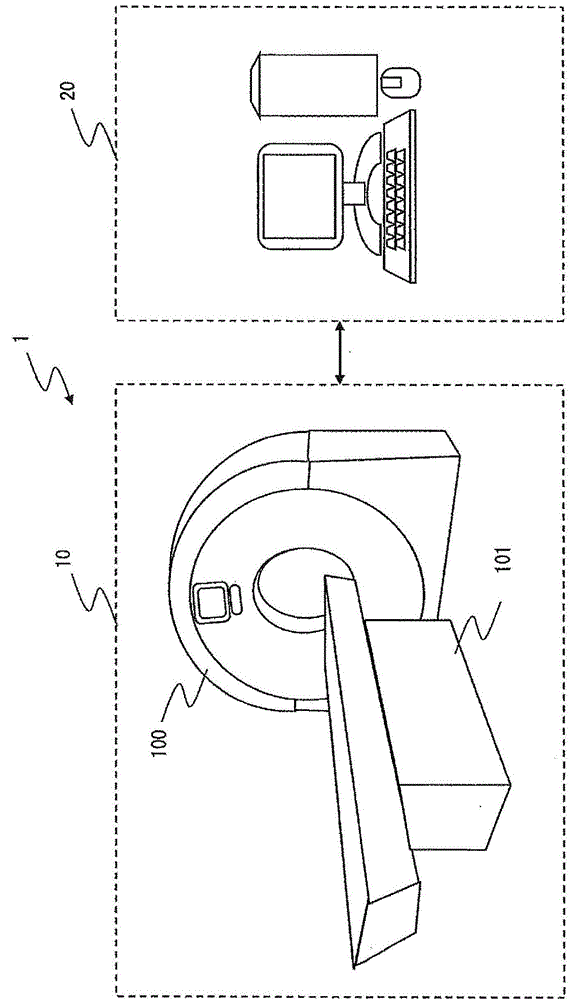
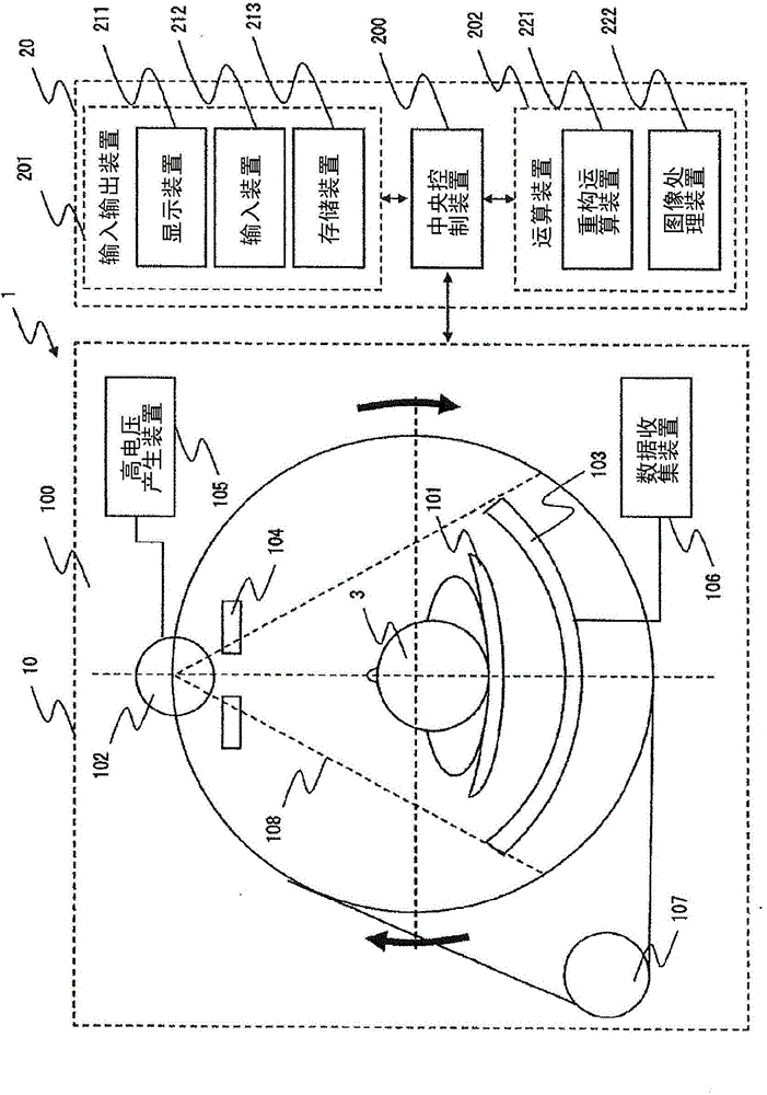
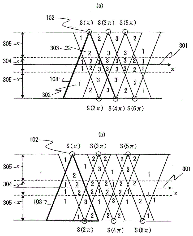

Image

  • X-ray CT device and image reconstruction method
  • X-ray CT device and image reconstruction method
  • X-ray CT device and image reconstruction method

Examples


Embodiment

[0253] Next, refer to Figure 20 ~ Figure 27 An example of the image reconstruction method of this embodiment will be described below. A comparative example is to set the backprojection phase width to a constant value as in the method of (Conventional Method 1) Patent Document 1 and set it to the narrowest value that can be used in the image, and as in (Conventional Method 2) Patent Document As in method 2, the backprojection phase width is set to a variable value for each pixel, and the value at which the most projection data can be used for each pixel is set.

[0254] In conventional method 1, the same back projection phase width is set for all pixels within the maximum FOV=500 mm. In conventional method 2, the maximum back-projection phase width is calculated for each pixel within the maximum FOV=500 mm. In the present invention, the reference position is defined as the rotation center position, and the backprojection phase width in each pixel is calculated so that it has...


PUM


Abstract

To generate a reconstructed image which is suited to characteristics of a site (especially a bilaterally symmetric site) and with which an appropriate image diagnosis is possible, a computation device (202): computes a back projection phase width (F1) at a rotational center (S102); computes a distance (R1) between the rotational center location which is a reference location and a pixel to be reconstructed (S103); according to the distance (R1) between the rotational center location and the pixel to be reconstructed, sets a function (f1) which changes the back projection phase width (S104); computes a back projection phase width (F2) in the pixel to be reconstructed, substituting a value of the distance (R1) between the rotational center location which is the reference location and a pixel to be reconstructed in the function (f1) which changes the back projection phase width (S105); computes a view weighting, on the basis of the back projection phase width (F2) in the post-correction pixel to be reconstructed and a slope width (gamma) of a view weighting function (S106); and reconstructs a CT image, using the view weighting (S107).

Description

technical field [0001] The present invention relates to irradiating an object with X-rays, measuring the X-rays transmitted through the object by an X-ray detector, and reconstructing the measurement data from multiple directions to obtain the X-rays of the reconstructed image of the object CT device, etc. In particular, the present invention relates to an X-ray CT apparatus and the like capable of controlling noise characteristics of reconstructed images. Background technique [0002] In general, the wider the angular width of projection data used in reconstruction (hereinafter referred to as "back-projection phase width"), the smaller the amount of noise in the reconstructed image. Conversely, the narrower the backprojection phase width, the greater the amount of noise in the reconstructed image. [0003] Patent Document 1 discloses a method of performing reconstruction using the same backprojection phase width regardless of the image position in order to perform reconst...

Claims


Application Information

Patent Timeline
Patent Type & Authority Applications(China)
IPC IPC(8): A61B6/03
CPCA61B6/032G06T11/006A61B6/5205G06T2211/412G06T5/00G06T7/0012G06T2207/10081
Inventor 后藤大雅高桥悠广川浩一
Owner HITACHI HEALTHCARE MFG LTD
Why Eureka
Try Eureka