Low pressure drop holding grid and fuel component with holding grid

A technology for maintaining grids and low pressure drop, applied in the field of nuclear reactors, can solve the problems of bad heat dissipation effect of fuel assemblies, large pressure loss of coolant fluid, etc., and achieve the effects of considerable material saving, small pressure loss, and reduction of the frontal flow area.

Active Publication Date: 2014-09-10
CHINA NUCLEAR POWER TECH RES INST CO LTD +1
View PDF5 Cites 4 Cited by
  • Summary
  • Abstract
  • Description
  • Claims
  • Application Information

AI Technical Summary

Problems solved by technology

[0004] The guide vanes in the prior art are arranged on the upper and lower edges of the outer strips of the holding grid and protrude obliquely toward the inside of the grid structure. The structure and arrangement of the guide vanes at the upper and lower ends of the outer strips are the same. When a lateral misalignment occurs during the hoisting process, the guide wings of adjacent holding grids may be hooked to each other, and the smaller the guide wings protrude into the grid structure, the higher the possibility of hooking. Therefore, the inward protruding range of the guide vanes needs to be set larger, and it is precisely because of this larger protruding structure that the guide vanes form a front-flow area in the flow direction of the coolant in the fuel assembly, and the front-flow area The existence of the coolant makes the pressure loss of the coolant fluid larger, which in turn adversely affects the heat dissipation in the fuel assembly

Method used


Image

  • Low pressure drop holding grid and fuel component with holding grid
  • Low pressure drop holding grid and fuel component with holding grid
  • Low pressure drop holding grid and fuel component with holding grid

Examples


Embodiment Construction

[0028] The preferred embodiments of the present invention will be described below in conjunction with the accompanying drawings.

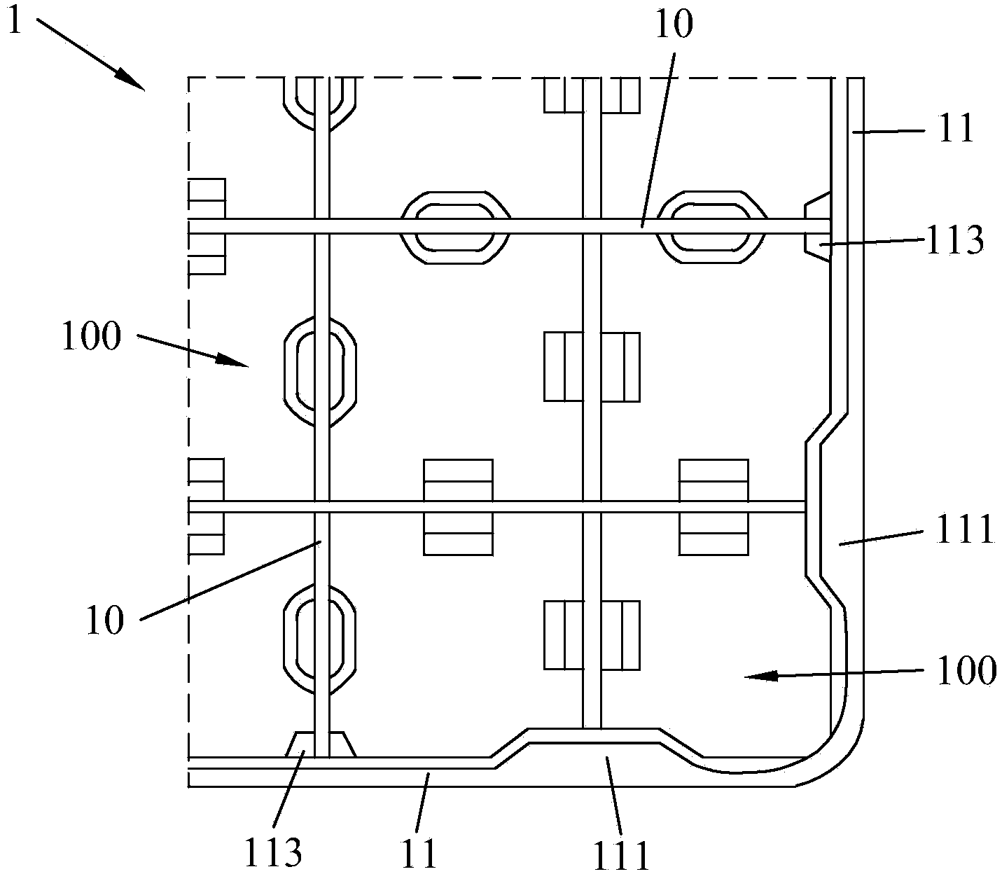
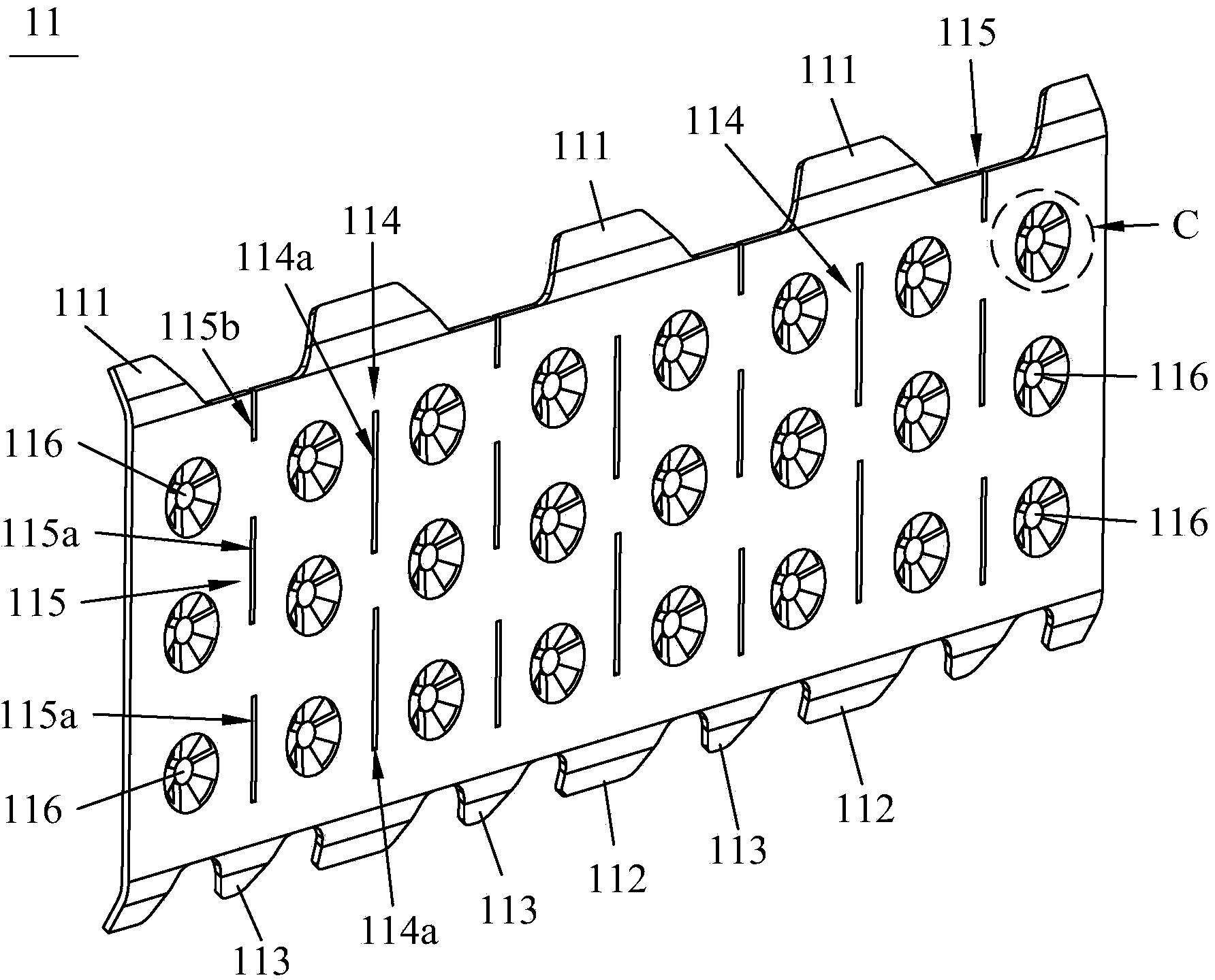
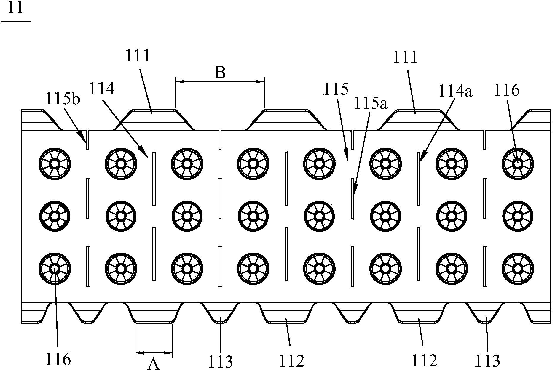
[0029] combine Figure 1 to Figure 3 As shown, the present invention provides a low-pressure drop holding grid 1 for light water reactor nuclear fuel assemblies, the holding grid 1 includes a plurality of inner strips 10 and outer strips 11, and a plurality of inner strips 10 cross each other to form a network The grid structure forms a plurality of hollow grid units 100 , and the outer strips 11 surround the grid structure and are fixed with the inner strips 10 . Except for a few grid units 100 which accommodate control rod guide tubes, most of the other grid units 100 accommodate a fuel rod. And the same rigid projections and springs as in the prior art can be set on the inner strip 10 to clamp the fuel rods.

[0030] The upper edge of the outer strip 11 forms a plurality of first guide wings 111 arranged at intervals, and the lower edge of the...


PUM


Abstract

The invention discloses a low pressure drop holding grid which comprises a plurality of inner strips and outer strips, wherein the plurality of inner strips are intersected with one another to form a net-shaped grid structure and are formed into a plurality of hollow grid units; the outer strips are arranged at the periphery of the grid structure in an enclosure manner and are fixed with the inner strips; a plurality of first guide wings which are arranged at intervals are formed on the upper edges of the outer strips; a plurality of second guide wings and third guide wings which are arranged alternatively are formed on the lower edges of the outer strips; each third guide wing is positioned between two adjacent second guide wings; the interval between each second guide wing and each third guide wing is smaller than the width of each first guide wing; the first guide wings, the second guide wings and the third guide wings all extend into the grid structure in an inclined and convex manner. By adopting the low pressure drop holding grid disclosed by the invention, hooking in hoisting is effectively prevented, and moreover through cooperation of three guide wings, the amplitude that the guide wings extend into the grid structure in the inclined and convex manner can be very small, so that the incident flow area is small, and the pressure loss of a coolant is small.

Description

technical field [0001] The invention relates to the technical field of nuclear reactors, in particular to a low pressure drop holding grid and a fuel assembly with the holding grid. Background technique [0002] A certain number of fuel rods are arranged at certain intervals (such as: 15×15 or 16×16, etc.) and fixed into a bundle, which is called a reactor fuel assembly. The reactor fuel assembly is mainly composed of an upper nozzle, a lower nozzle, and a holding grid ( Also known as mixing grid or positioning grid), control rod guide tube and fuel rods. Among them, the holding grid is used for loading and positioning fuel rods and is composed of a plurality of inner strips and outer strips, and the plurality of inner strips are orthogonal to each other to form a grid-like grid structure with a plurality of grid units, while the outer The straps are fixedly surrounded by the inner straps. Except a few grid units are used to set the control rod guide tubes, each of the rem...

Claims


Application Information

Patent Timeline
IPC IPC(8): G21C3/34
CPCY02E30/40Y02E30/30
Inventor 陈晓明禹文池李伟才周跃民王嘉远钱昕
Owner CHINA NUCLEAR POWER TECH RES INST CO LTD
Why Eureka
Try Eureka