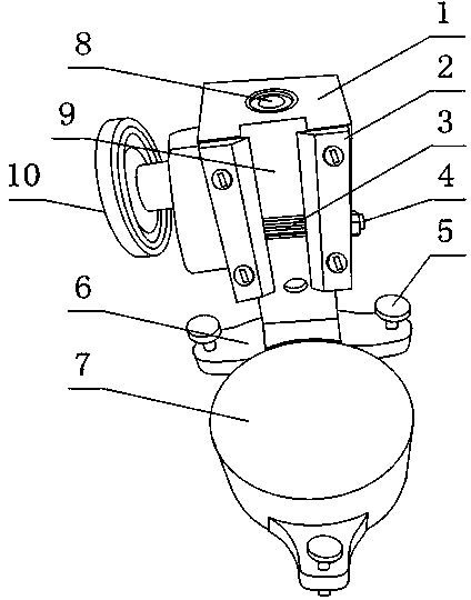
Rack device for Shore hardness tester
A technology of Shore hardness and hardness tester, which is applied in the field of Shore hardness tester bench device, can solve the problems of inconvenient and precise control of the position accuracy of the Shore hardness tester, affecting the perpendicularity of the strike pin and the material table, etc., and achieves a simple and optimized structure. The effect of measurement accuracy and easy height adjustment
- Summary
- Abstract
- Description
- Claims
- Application Information
AI Technical Summary
Problems solved by technology
Method used
Image
Examples
Embodiment 1
[0022] Such as figure 1 , The Shore hardness tester bench device provided by the present invention includes a base 6 and a material table 7 set on the base 6, and also includes a vertical fixing base 1, and the lower end of the fixing base 1 is fixedly connected to the base 6 , The fixing seat 1 is also provided with a durometer groove 9 in the vertical direction, and the durometer groove 9 is located above the material table 7;
[0023] The fixed seat 1 is also provided with a spline shaft 3 whose axial direction is in the horizontal direction, the spline shaft 3 protrudes relative to the bottom surface of the hardness tester groove 9 and the spline shaft 3 can rotate around its axis;
[0024] The base 6 is also provided with at least three leveling bolts 5 whose axis directions are in the vertical direction, and the leveling bolts 5 are not on the same straight line.
[0025] The hardness tester groove 9 in the above arrangement is used to house the Shore hardness tester, the spli...
Embodiment 2
[0027] This embodiment is further limited on the basis of embodiment 1: figure 1 The cross section of the hardness tester groove 9 is rectangular, and the fixing seat 1 is also provided with two ribs 2 bolted to it and arranged vertically, and the two ribs 2 are respectively located on different sides of the hardness tester groove 9 , And the distance between the ribs 2 is smaller than the width of the durometer groove 9.
[0028] The durometer groove 9 of the above structure is matched with the rib 2 to facilitate the fixing of the Shore hardness tester in the direction perpendicular to the height of the durometer groove 9 of the present invention: the side surface of the durometer groove 9 and the rib 2 are restricted to make Shore hardness The hardness tester can only move along the height direction of the hardness tester groove 9. More importantly, in the above structure, the brake of the Shore hardness tester and the present invention fails or the Shore hardness tester with ...
Embodiment 3
[0030] This embodiment is further limited on the basis of embodiment 1: figure 1 In order to facilitate the braking of the spline shaft 3, it also includes a hand wheel 10 connected with the spline shaft 3 and used for driving the spline shaft 3 to rotate around its axis.
[0031] In order to facilitate the fixation of the Shore hardness tester and the present invention, the spline shaft 3 is also provided with an external thread section, the external thread section is engaged with a positioning nut 4, and the positioning nut 4 is connected to the fixing seat 1. contact. That is, the above purpose is achieved by locking the spline shaft 3.
PUM
 Abstract
Description
Claims
Application Information
 - R&D Engineer
- R&D Manager
- IP Professional
- Industry Leading Data Capabilities
- Powerful AI technology
- Patent DNA Extraction
Browse by: Latest US Patents, China's latest patents, Technical Efficacy Thesaurus, Application Domain, Technology Topic, Popular Technical Reports.
© 2024 PatSnap. All rights reserved.Legal|Privacy policy|Modern Slavery Act Transparency Statement|Sitemap|About US| Contact US: help@patsnap.com


