Pressure device for locking mould

A pressure device and mold clamping technology, applied in the field of mold clamping mechanism, can solve problems such as damaged oil leakage, high pressure bladder manufacturing requirements, etc., and achieve the effects of good sealing, good mold clamping and pressure keeping effect, and reduced manufacturing cost.

Inactive Publication Date: 2014-09-10
王咏梅 +5
View PDF6 Cites 0 Cited by
  • Summary
  • Abstract
  • Description
  • Claims
  • Application Information

AI Technical Summary

Problems solved by technology

[0007] However, the pressure device for clamping the mold has relatively high requirements for the manufacture of the pressure bladder, especially the bonding requirements between the two wall pieces of the pressure bladder are very high, and it needs to maintain a good sealing bond under a certain pressure and stability, otherwise it will break and leak oil

Method used


Image

  • Pressure device for locking mould
  • Pressure device for locking mould
  • Pressure device for locking mould

Examples


Embodiment 1

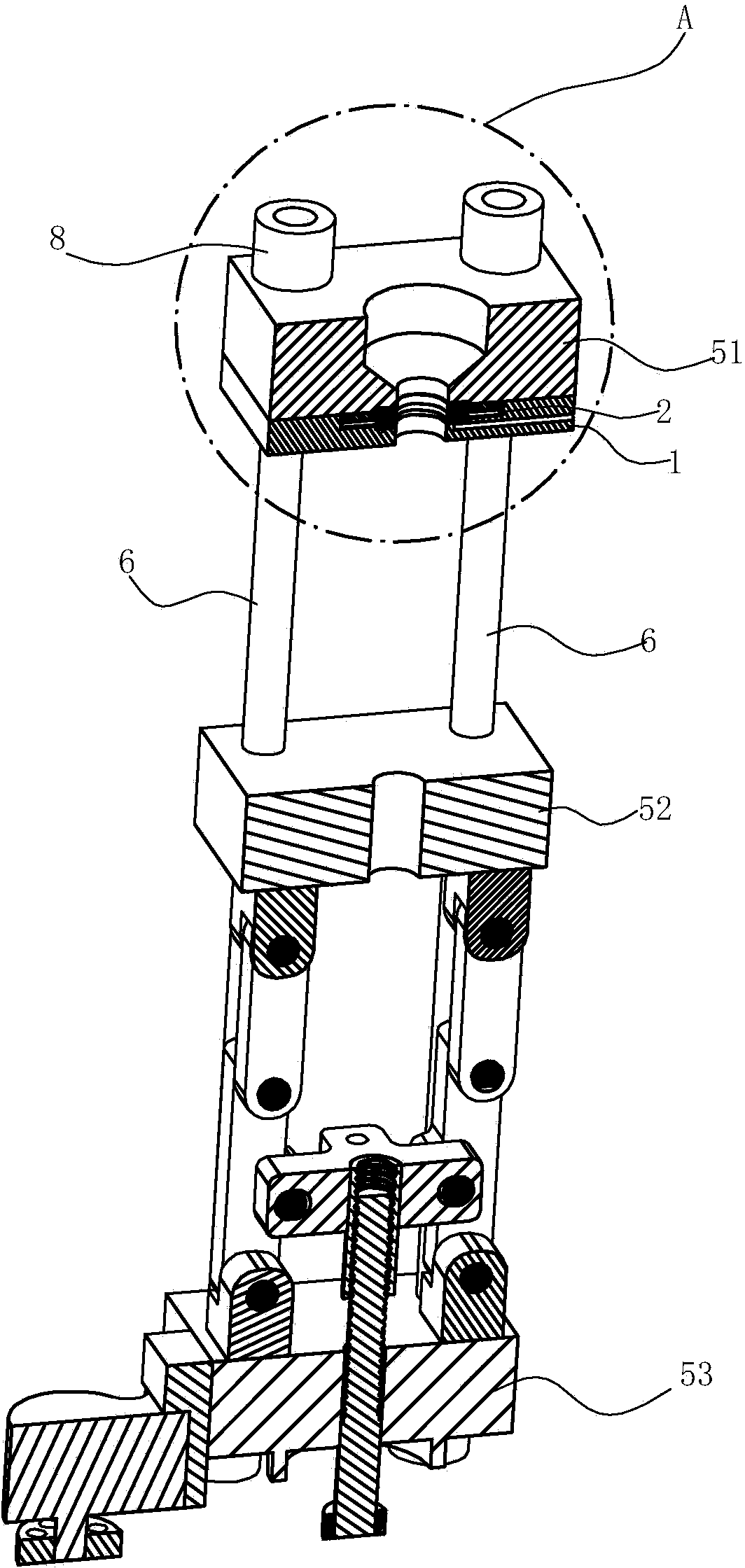
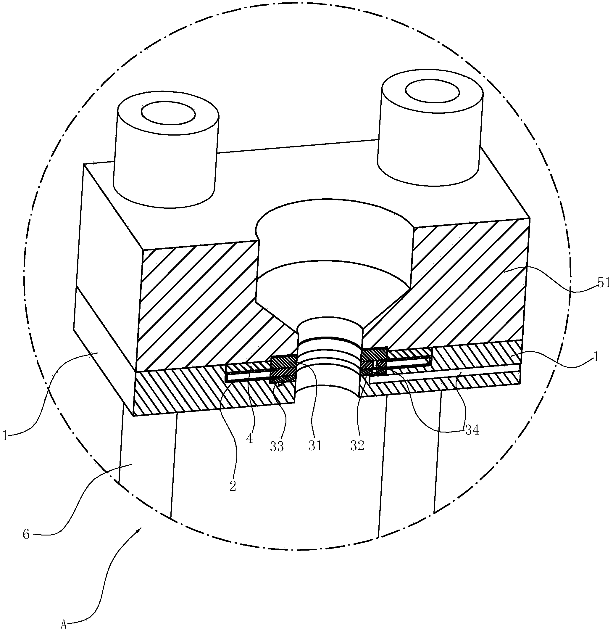
[0021] Such as figure 1 with figure 2 As shown, the pressure device for clamping includes:

[0022] The push plate 1 is arranged on the inner surface of the fixed mold plate 51 opposed to the movable template 52. The push plate 1 is provided with a groove, and the pressure bag 2 is accommodated in the groove.

[0023] The pressure bladder 2 can be filled with a pressure medium, such as hydraulic oil or compressed air. In this embodiment, it is made of plastic material, and it can also be made of other elastic materials suitable for bladder. The pressure bladder 2 is an integrally formed sheet-like structure. After the upper layer and the lower layer of the pressure bladder are laminated, a ring structure with an open inner edge is formed. The inner end edge of the upper layer is squeezed between the first fixing ring 31 and the second fixing ring 32, and the inner end edge of the lower layer is squeezed between the second fixing ring 32 and the third fixing ring 33 to form a seali...

Embodiment 2

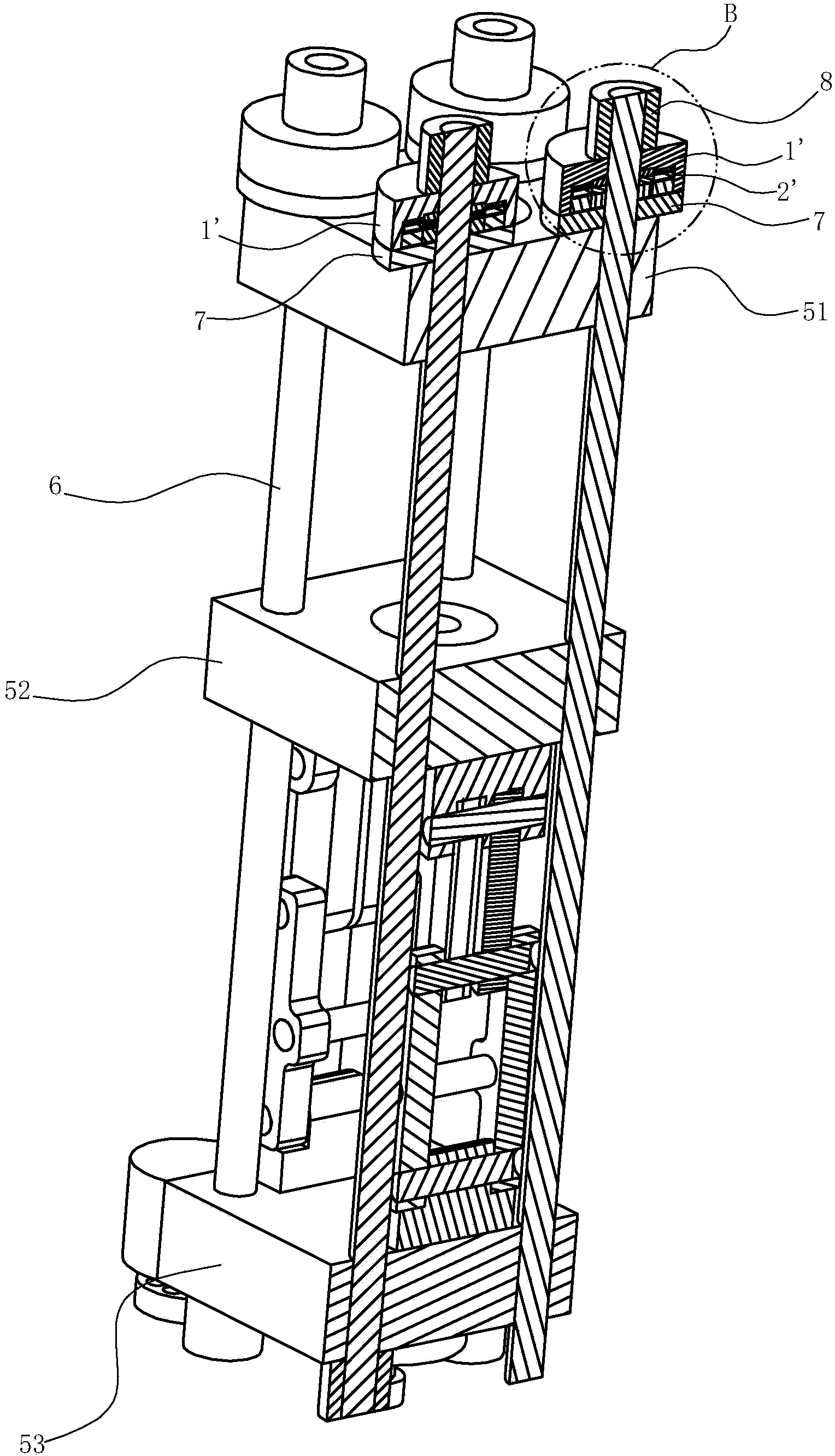
[0029] Such as image 3 with Figure 4 As shown, the fixed mold plate 51 and the movable mold plate 52 are connected together by four tie rods 6. These four tie rods 6 are not only the connecting parts of the fixed mold plate 51 and the movable mold plate 52, but also the guide parts of the movable mold plate when the mold is opened and closed. There are four sets of pressure devices for mold clamping, which are set corresponding to the four tie rods 6 respectively. The structure of each clamping device is the same.

[0030] Each clamping pressure device includes:

[0031] The bottom plate 7 is a ring structure, which is arranged on the tie rod 6 and abuts against the outer surface of the fixed template 51 away from the movable template. A push plate 1'is connected to the outer end surface of the bottom plate 7, and a groove is provided on the push plate 1', and the pressure bag 2'is accommodated in the groove. A second thrust ring 4'is also provided in the groove, and the secon...


PUM


Abstract

The invention relates to a pressure device for locking a mould. The pressure device comprises a template and a push plate which are arranged on a mould opening and closing mechanism, wherein pressure bags (2, 2') are arranged between the template and the push plate. The pressure is characterized in that the pressure bags (2, 2') are integrally molded; the inner end edges of the upper layers of the pressure bags are squeezed between a first fixing ring (31) and a second fixing ring (32); the inner end edges of the lower layers of the pressure bags are squeezed between the second fixing ring (32) and a third fixing ring (33); the first fixing ring (31), the second fixing ring (32) and the third fixing ring (33) are detachably connected together; the second fixing ring (32) is provided with a channel (34) which is used for communicating inner cavities of the pressure bags with an outer pressure medium source. The pressure device is low in manufacturing cost, convenient to use, small in energy consumption, rapid in pressure boosting, good in pressure-keeping effects, long in service life and convenient to assemble and disassemble.

Description

Technical field [0001] The invention relates to a clamping mechanism of a mold forming machine such as an injection molding machine and a die casting machine, and specifically refers to a pressure device for clamping a mold. Background technique [0002] Mold forming machines such as injection molding machines and die casting machines use molds to produce products with complex shapes. Therefore, these machines have an opening and closing mechanism. The mold is installed in the opening and closing mechanism. The product needs to be opened and closed during the molding process. The mold mechanism closes and locks the mold to complete the molding of the product and obtain a qualified product. [0003] There are usually two types of mold opening and closing mechanisms currently in use, one is a hydraulic cylinder direct pressure mold opening and closing mechanism, and the other is a toggle lever mechanical mold opening and closing mechanism. [0004] The hydraulic cylinder direct pressu...

Claims


Application Information

Patent Timeline
IPC IPC(8): B29C45/68B22D17/26
CPCB22D17/263B22D17/266B29C45/68
Inventor 陈国永
Owner 王咏梅
Why Eureka
Try Eureka