Machine tool loading and unloading silo

A machine tool and silo technology, applied in the field of machine tool loading and unloading silos, can solve the problems of reducing the feeding capacity of the feeding device, reducing production efficiency, increasing the number of workpiece pallets, etc., achieving high reliability and improving the effect of feeding capacity

Active Publication Date: 2016-06-08
CHONGQING MACHINE TOOL GROUP
View PDF5 Cites 5 Cited by
  • Summary
  • Abstract
  • Description
  • Claims
  • Application Information

AI Technical Summary

Problems solved by technology

[0003] 1. Since the horizontal baffle can only block the pallet at the grabbing position, when the pallet at the grabbing position stays, other trays may collide with the pallet at the grabbing position as the support top plate moves, and in order to prevent collisions , you need to reduce the number of trays, or constantly adjust the position between other trays and the grabbing tray, which will reduce the feeding capacity of the feeding device;
[0004] 2. The existing pallet can only meet the clamping requirements of one type of workpiece. Due to the variety of workpiece models and structures, when other types of workpieces need to be clamped, the entire workpiece pallet needs to be replaced, which is complicated to operate and reduces production efficiency; In addition, since each type of workpiece needs to be equipped with a corresponding workpiece pallet, the number of workpiece pallets is greatly increased, which increases the investment cost

Method used


Image

  • Machine tool loading and unloading silo
  • Machine tool loading and unloading silo
  • Machine tool loading and unloading silo

Examples


Embodiment Construction

[0034] The preferred embodiments of the present invention will be described in detail below with reference to the accompanying drawings.

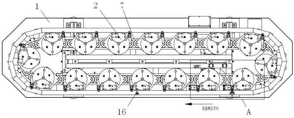
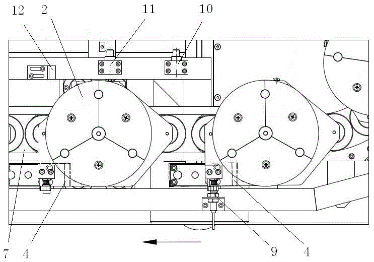
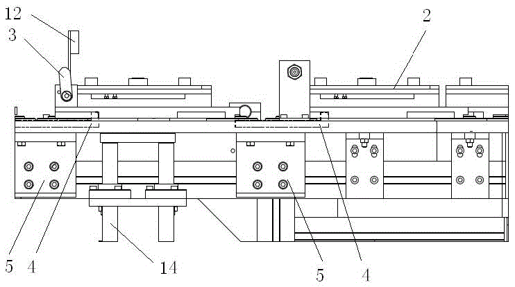
[0035] like figure 1 As shown, it is a structural schematic diagram of an embodiment of the loading and unloading bin of the machine tool of the present invention. The loading and unloading hopper of the machine tool in this embodiment includes a frame 1, on which a conveying device is arranged, and on the conveying device, a workpiece pallet 2 which is frictionally matched with it and is used for clamping workpieces is arranged at intervals, and the workpiece pallet 2 is provided with a For the state pointer 3 indicating whether there is a clamped workpiece and has two position states, two baffle mechanisms for limiting the position of the workpiece tray 2 are provided on the frame 1. The plate 4 and the baffle cylinder 5 used to drive the movement of the baffle 4, the conveying device area between the two baffles 4 is the workpiece grabb...


PUM


Abstract

A machine tool feeding and discharging bin comprises a rack. A conveying device is arranged on the rack. Workpiece trays are arranged on the conveying device at intervals and provided with state pointers. Two baffle mechanisms are arranged on the rack and respectively comprise a baffle and a baffle air cylinder. The area, between the two baffles, of the conveying device is a workpiece grabbing area, and in the moving direction of the conveying device, the staying position of the workpiece trays matched with the rear baffle is a workpiece grabbing position. The machine tool feeding and discharging bin further comprises a control system. The control system comprises a controller, a proximity switch I used for detecting the position state of the state pointers, a proximity switch II used for detecting whether the workpiece trays enter the workpiece grabbing area and a proximity switch III used for detecting whether the workpiece trays arrive at the workpiece grabbing position. A reflection switch corresponding to the workpiece grabbing position is arranged on the rack. A reversing solenoid valve I electrically connected with the controller is arranged on the air path of the baffle air cylinders. The proximity switch I, the proximity switch II, the proximity switch III and the reflection switch are electrically connected with the controller.

Description

technical field [0001] The invention relates to an auxiliary device of a machine tool, in particular to a machine tool loading and unloading hopper. Background technique [0002] The Chinese patent with the publication number CN102513867A discloses a machine tool loading and unloading feeding device. The machine tool loading and unloading feeding device includes a reducer on the left side of the middle plate. The driving sprocket at the upper end of the output shaft of the reducer passes through the chain and the driven chain The driven sprocket is set on the vertical support shaft on the right part of the middle plate through the bearing; above the chain, there is a pair of through-shooting switches for collecting the signal of the workpiece reaching the grasping position, and the chain has a supporting top plate , a tray is placed on the supporting top plate, and the workpiece bracket is installed on the tray; a cylinder is arranged on the middle plate from front to back, ...

Claims


Application Information

Patent Timeline
Patent Type & Authority Patents(China)
IPC IPC(8): B23Q7/00
CPCB23Q7/003
Inventor 刘一冉蒋林李云贵高槐唐岷
Owner CHONGQING MACHINE TOOL GROUP
Why Eureka
Try Eureka