
Node network monitoring method and device

A node network and monitoring device technology, which is applied in the field of node network monitoring methods and devices, can solve the problems of cumbersome, inability to check the status of network equipment and line conditions in multi-level jumps, complex network monitoring operations, etc.

Active Publication Date: 2014-09-03
TRAVELSKY
View PDF3 Cites 9 Cited by
  • Summary
  • Abstract
  • Description
  • Claims
  • Application Information

AI Technical Summary

Problems solved by technology

Specific to the individual monitoring of devices such as routers, due to inconsistent MIB library information, it is necessary to modify the MIB value of the corresponding monitoring point in the underlying configuration file during commercial software deployment, and it is not possible to check the status of network devices and line conditions in multi-level jumps, making the network Monitoring operations are very complex and cumbersome

Method used


Image

  • Node network monitoring method and device
  • Node network monitoring method and device

Examples


Embodiment Construction

[0067] In order to make the purpose, technical solutions and advantages of the embodiments of the present invention clearer, the technical solutions in the embodiments of the present invention will be clearly and completely described below in conjunction with the drawings in the embodiments of the present invention. Obviously, the described embodiments It is a part of embodiments of the present invention, but not all embodiments. Based on the embodiments of the present invention, all other embodiments obtained by persons of ordinary skill in the art without making creative efforts belong to the protection scope of the present invention.

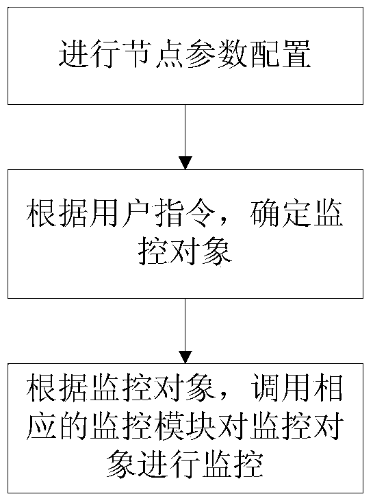
[0068] figure 1 A schematic flow diagram of a node network monitoring method provided by an embodiment of the present invention, such as figure 1 As shown, the node network monitoring method of this embodiment includes:

[0069] Step 1: Configure node parameters;

[0070] Optionally, in step 1, configure router port parameters, including: ...


PUM


Abstract

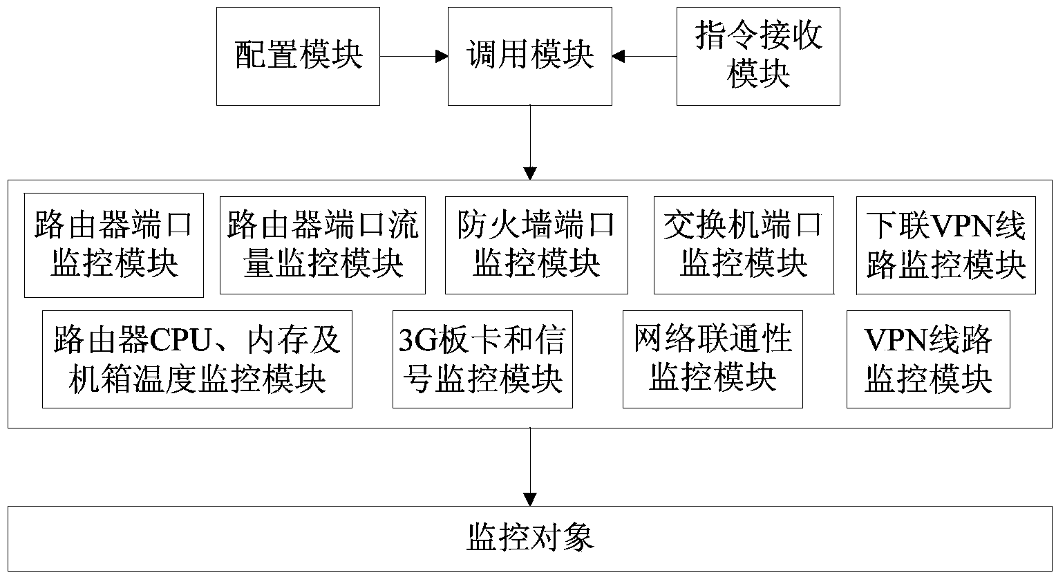
The invention provides a node network monitoring method and device. The method comprises the steps that first, node parameter configuration is carried out; second, a monitored object is determined according to a user instruction; third, a corresponding monitoring module is called to monitor the monitored object according to the monitored object. The node network monitoring method and device can monitor various cascade network devices; in addition, the node network monitoring method and device can skip to network devices of downlink small nodes step by step to test downlink routers and the situation of VPN lines.

Description

technical field [0001] The invention relates to the field of network monitoring, in particular to a node network monitoring method and device. Background technique [0002] At present, most network monitoring software uses the SNMP protocol to read and trigger network devices in the form of get and set, and display data in the form of web pages. The development language used is usually java. When deploying software, it is necessary to install monitoring Dedicated server, server operating environment and parameter configuration are difficult. When adapting to the civil aviation information network, commercial software is greatly restricted in terms of configuration, application deployment and network adaptability. Specific to the individual monitoring of devices such as routers, due to inconsistent MIB library information, it is necessary to modify the MIB value of the corresponding monitoring point in the underlying configuration file during commercial software deployment, ...

Claims


Application Information

Patent Timeline
IPC IPC(8): H04L12/24H04L12/46H04L29/06
Inventor 蔡毅
Owner TRAVELSKY
Learn More