
Substrate positioning device

A positioning device and substrate technology, applied in electrical components, semiconductor/solid-state device manufacturing, circuits, etc., can solve the problems of increasing the design and production cost of automated substrate positioning equipment, and achieve the effect of reducing production costs

Inactive Publication Date: 2014-09-03
MAS AUTOMATION CORP
View PDF4 Cites 3 Cited by
  • Summary
  • Abstract
  • Description
  • Claims
  • Application Information

AI Technical Summary

Problems solved by technology

[0002] Generally speaking, the substrate refers to the plate-shaped object used in the manufacture of solar panels or circuit boards. Before the substrate is processed, the position of the substrate must be fixed to prevent the substrate from being displaced during processing and losing processing. The phenomenon of precision, generally speaking, the industries related to the production and manufacturing of substrates have adopted automated tools to transfer and position the substrates. etc.) plus driving elements (such as motors, pneumatic cylinders, etc.), use sensing elements to detect the current position of the substrate, and then drive and adjust the substrate to the required position through the driving element. However, this method must be used in conjunction with more Complicated control circuits can effectively control the automatic operation accuracy between related sensing elements, drive elements and substrates, and relatively easy to increase the design and production costs of automated substrate positioning equipment

Method used


Image

  • Substrate positioning device
  • Substrate positioning device
  • Substrate positioning device

Examples


Embodiment Construction

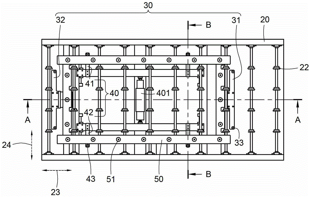
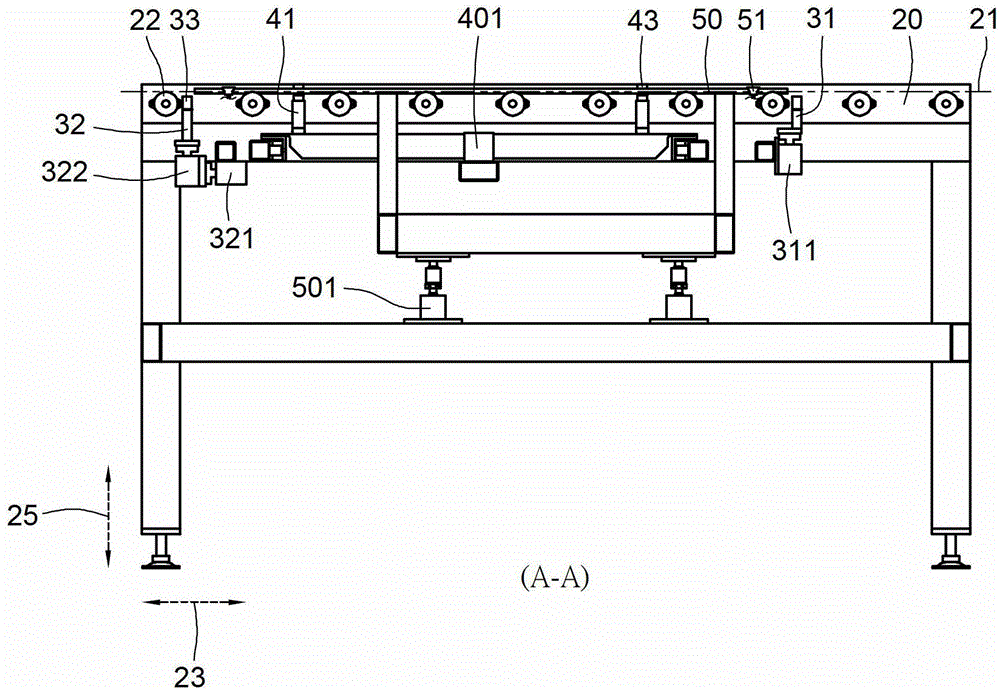
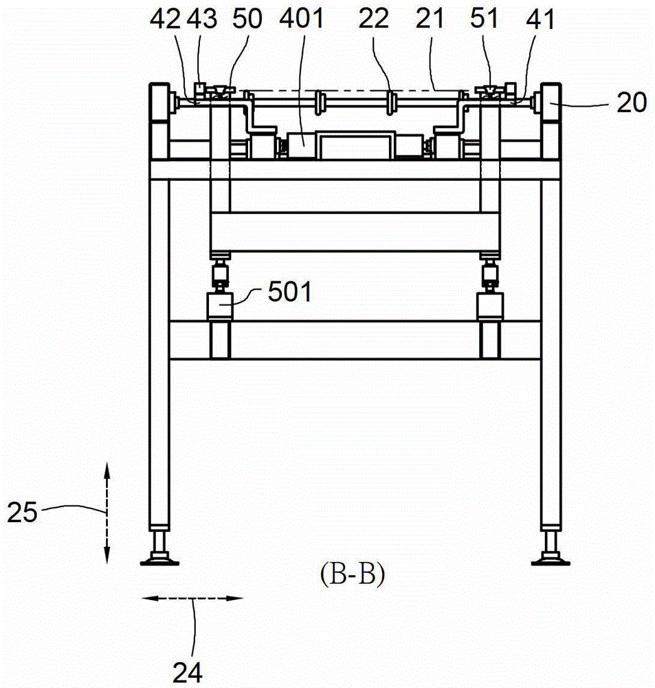
[0025] The purpose of implementing the substrate positioning device of the present invention is to use mechanical components to stop and position the substrate, instead of traditionally using a combination of sensing elements and driving elements to position the substrate. Please refer to figure 1 , figure 2 and image 3 , illustrating an embodiment of the present invention, is to provide a substrate positioning device. in, figure 1 A schematic diagram of the configuration of the substrate positioning device of the present invention is revealed, figure 2 revealed figure 1 The A-A sectional schematic diagram, image 3 reveals the execution figure 1 A schematic diagram of the B-B section. in:

[0026] A reference surface 21 is formed on the conveyor 20, and the reference surface 21 is formed by a plurality of rollers 22 that are pivotally arranged on the conveyor 20 and distributed on a plane. A displacement in the horizontal direction 23 , in practice, the substrate ...


PUM


Abstract

Provided is a substrate positioning device, comprising a datum plane which can transmit substrates one by one and moves horizontally. Firstly, an end positioner stops the movable substrate of the datum plane, and then a side edge positioned contacts with and corrects the substrate of the datum plane, and finally a lifter lifts the substrate to leave the datum plane through movement from bottom up. The device stops and positions the substrate through mechanical assemblies, so as to remove configuration of sensing components.

Description

technical field [0001] The invention relates to a substrate positioning technology, in particular to a substrate positioning device. Background technique [0002] Generally speaking, the substrate refers to the plate-shaped object used in the manufacture of solar panels or circuit boards. Before the substrate is processed, the position of the substrate must be fixed to prevent the substrate from being displaced during processing and losing processing. The phenomenon of precision, generally speaking, the industries related to the production and manufacturing of substrates have adopted automated tools to transfer and position the substrates. etc.) plus driving elements (such as motors, pneumatic cylinders, etc.), use sensing elements to detect the current position of the substrate, and then drive and adjust the substrate to the required position through the driving element. However, this method must be used in conjunction with more Complicated control circuits can effectively...

Claims


Application Information

Patent Timeline
Patent Type & Authority Applications(China)
IPC IPC(8): H01L21/68
CPCH01L21/68
Inventor 韩进隆王渊民
Owner MAS AUTOMATION CORP
Learn More