
Start-up burner igniter nitrogen protection device

A technology of nitrogen protection device and start-up burner, which is applied in the direction of combustion ignition, burner, ignition by electric spark, etc., which can solve the problems of ensuring the safety of the ignition rod head, the large impact of the ignition rod head, and the easy carbonization of sealing materials. , to prevent the danger of carbonization, easy to operate, and prevent radiation

Active Publication Date: 2016-02-03
XIAN AEROSPACE SOURCE POWER ENG CO LTD
View PDF8 Cites 0 Cited by
  • Summary
  • Abstract
  • Description
  • Claims
  • Application Information

AI Technical Summary

Problems solved by technology

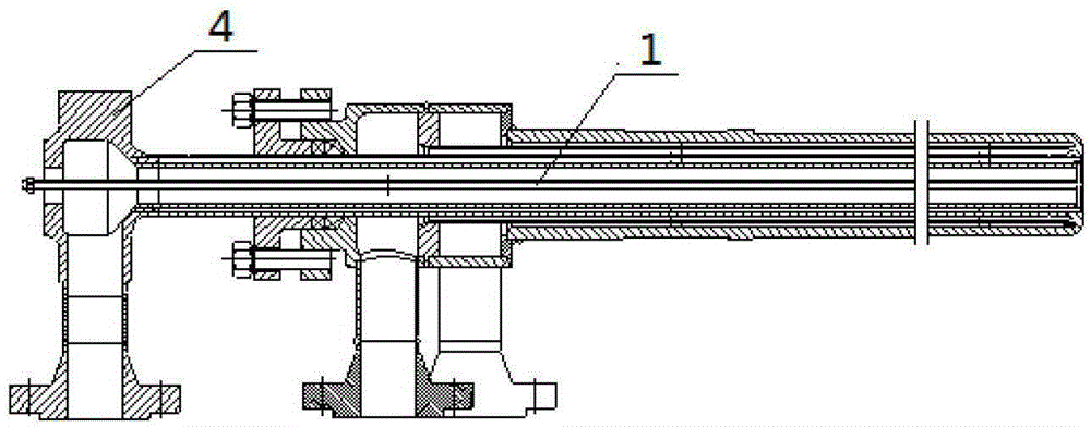
The structure of the integrated start-up burner known in the art is as attached figure 1 As shown, the ignition rod 1, the main ignition element of the high-energy igniter, is installed at the center of the start-up burner 4. The existing problems are: the high-temperature radiation during the work of the start-up burner and the local tempering at the moment of the SUB closing are on the ignition. The impact of the head of the rod is relatively large (it is easy to cause the ignition head to be burned), which always threatens the safety of the igniter; the method used to solve the above problems in the past is to set a sealing material (such as epoxy resin, etc.) on the head of the ignition rod, but The sealing material is easy to carbonize, so this method cannot really effectively guarantee the safety of the ignition rod head

Method used


Image

  • Start-up burner igniter nitrogen protection device
  • Start-up burner igniter nitrogen protection device

Examples


Embodiment Construction

[0012] The content of the present invention will be further described below in conjunction with the accompanying drawings, but the practical application structure of the present invention is not limited to the following embodiments.

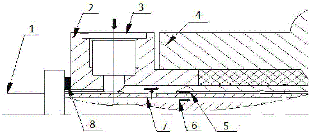
[0013] Referring to the accompanying drawings, the start-up burner igniter nitrogen protection device according to the present invention includes a sleeve 2 and an ignition rod 1 fitted on the start-up burner 4, the sleeve 2 is set on the rear part of the center channel of the start-up burner 4, and the ignition The rod 1 passes through the sleeve 2 and is pushed in from the tail of the start-up burner 4, and extends to the head of the burner through the central channel of the start-up burner 4. The side wall of the barrel 2 is provided with a nitrogen inlet 3 leading into the central channel of the start-up burner 4, and a nitrogen inlet 7 is provided on the rear wall of the ignition rod 1. In actual work, before the start-up burner runs, the pr...


PUM


Abstract

The invention relates to a startup burner igniter nitrogen protecting device which is provided with a sleeve and an ignition rod. The sleeve is arranged on the back portion of a startup burner center channel in a sleeved mode. The ignition rod is inserted into the startup burner center channel from the back end of the sleeve. A nitrogen inlet which is communicated with the startup burner center channel is formed in the side wall of the sleeve. A nitrogen entering opening is formed in the rod wall on the back portion of the ignition rod. In practical working, before startup burner operation, protecting nitrogen enters the ignition rod through the sleeve nitrogen inlet, and the protecting nitrogen is sprayed out through the head of the ignition rod in two ways. During startup burner operation, the head of the ignition rod is completely surrounded by nitrogen so that the head of the ignition rod can be effectively protected, and the influence from high-temperature airflow radiation is avoided. At a flameout stage, nitrogen pressure in the ignition rod is higher than external environment pressure, tempering of the head of the ignition rod can be effectively avoided, and safe operation of the ignition rod can be guaranteed. The startup burner igniter nitrogen protecting device has the advantages of being reasonable in structure and convenient to operate, and the service life of the ignition rod can be effectively prolonged.

Description

technical field [0001] The content of the present invention belongs to the technical field of coal gasification equipment, and relates to a nitrogen protection device for a burner igniter during operation. Background technique [0002] As the core equipment of the ignition start-up device, the integrated start-up burner mainly plays the role of raising the temperature and pressure of the dry powder pressurized coal gasification device. Before the start-up of the gasification device, the start-up burner is pushed into the set position inside the furnace by the propulsion mechanism through the central control DCS or the on-site cabinet control. When the ignition start-up command is issued, each pipeline of the burner starts to be filled with inert gas (nitrogen ) for purging, and then filled with fuel and oxidant, when the fluid involved in combustion is sprayed out at the head under pressure build-up, the high-energy electric ignition device starts to work and ignites the sta...

Claims


Application Information

Patent Timeline
Patent Type & Authority Patents(China)
IPC IPC(8): F23D11/36F23Q3/00
Inventor 薛康武红京刘自涛
Owner XIAN AEROSPACE SOURCE POWER ENG CO LTD
Learn More