Material conveying base of steel band rolling-up machine

A technology of winding machine and base, which is applied in the directions of winding strips, thin material handling, transportation and packaging, etc. It can solve the problems of laborious and difficult unloading and transportation, and achieve the effect of simple structure and convenient transportation and unloading

Active Publication Date: 2014-09-03
绩溪徽腾机械有限公司
View PDF6 Cites 2 Cited by
  • Summary
  • Abstract
  • Description
  • Claims
  • Application Information

AI Technical Summary

Problems solved by technology

[0002] During the production of the blade, the scrap steel strip cut from the blade mold must be recycled through the winder, and the scrap steel sheet recovered on the main shaft of the winder is laborious and difficult to unload and transport due to its high quality

Method used


Image

  • Material conveying base of steel band rolling-up machine
  • Material conveying base of steel band rolling-up machine
  • Material conveying base of steel band rolling-up machine

Examples


Embodiment Construction

[0016] The technical solutions of the present invention will be further described below in conjunction with the accompanying drawings and through specific implementation methods.

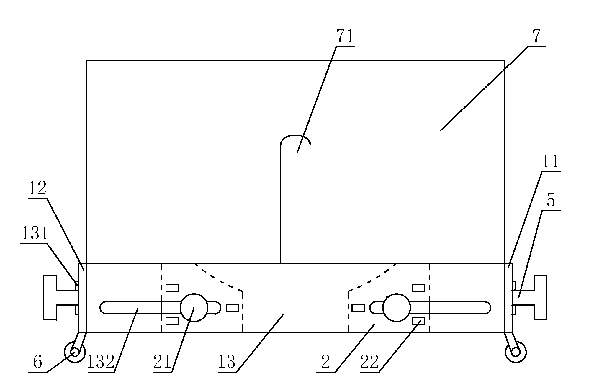
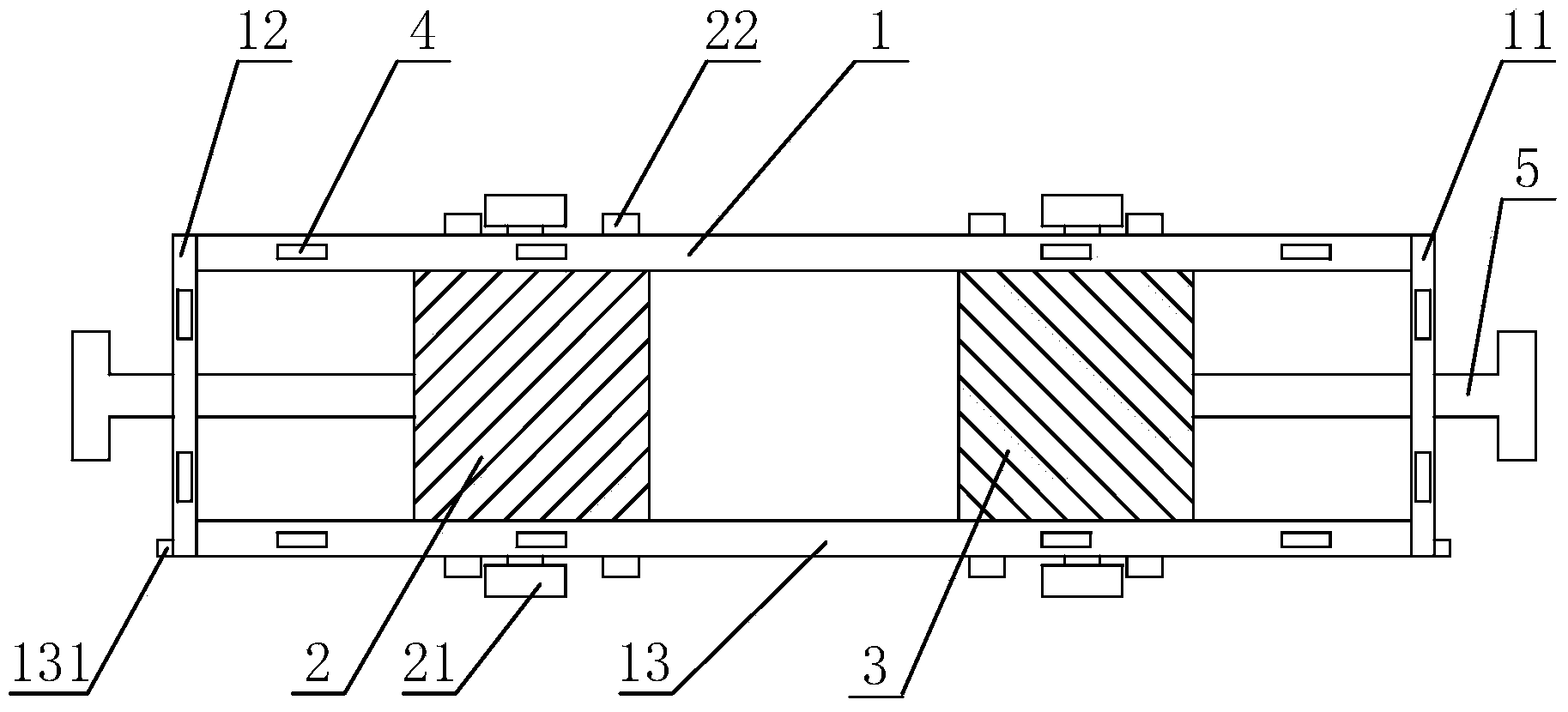
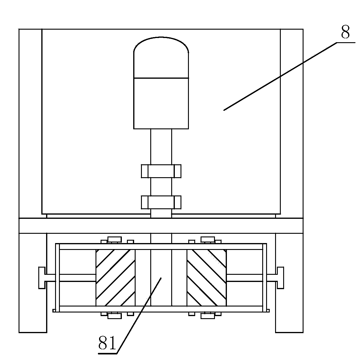
[0017] Such as Figure 1 to Figure 4 As shown, the material transport base of the steel strip winder includes the surrounding side plates, the left positioning block 2, the right positioning block 3 and the baffles arranged on the surrounding side plates, the left side plate 12, the right side plate 11 is integrally fixedly connected with the rear side plate 1, a pair of protrusions 131 are provided on both sides of the front side plate 12, grooves are opened at corresponding positions on the left side plate 12 and the right side plate 11, and the protrusions 131 are stuck in the In the groove, the front side plate 13 is clamped and fixed with the left side plate 12 and the right side plate 11. There are slots 4 above the side plates, and the clamping block 72 provided below the baffle plate is used...


PUM


Abstract

The invention discloses a material conveying base of a steel band rolling-up machine. The material conveying base of the steel band rolling-up machine resolves the problem that material unloading and conveying of a traditional steel piece rolling-up machine are difficult. The material conveying base of the steel band rolling-up machine comprises lateral plates on the four sides, a left positioning block, a right positioning block and baffles, wherein the left lateral plate and the right lateral plate are fixedly and integrally connected with the rear lateral plate and are fixedly connected with the front lateral plate in a clamping mode, clamping grooves are formed in the upper portions of the lateral plates, clamping blocks are arranged under the baffles in a matched mode to be connected with the baffles in a clamping mode, a relief groove matched with a main shaft of the rolling-up machine is formed in the rear baffle, the left side and the right side of the front lateral plate and the left side and the right side of the rear lateral plate are respectively and symmetrically provided with a pair of kidney-shaped holes, the two ends of the left positioning block and the two ends of the right positioning block are respectively erected in the kidney-shaped holes correspondingly formed in the front lateral plate and the rear lateral plate, the left positioning block and the right positioning block are used for positioning a steel band coil, are fixed and positioned on the front lateral plate and the rear lateral plate through positioning pins, and are provided with pull rods, and wheels are fixed under the left lateral plate and the right lateral plate. The material conveying base is simple in structure, and can unload and convey materials conveniently.

Description

technical field [0001] The invention relates to a material conveying base of a steel strip winder. Background technique [0002] In the process of producing blades, the scrap steel strips cut from the blade molds must be recycled through the winder, and the scrap steel coils recovered on the main shaft of the winder are relatively laborious and difficult to unload and transport due to their high quality. Contents of the invention [0003] The object of the present invention is to provide a material transport base of a steel strip coiler which is convenient for unloading and transporting scrap steel coils. [0004] For reaching this purpose, the present invention adopts following technical scheme: [0005] A material transport base for a steel strip winder, the base includes side plates around, left positioning blocks, right positioning blocks and baffle plates, the left and right side plates are integrally fixedly connected to the rear side plates, The left and right sid...

Claims


Application Information

Patent Timeline
Patent Type & Authority Applications(China)
IPC IPC(8): B65H19/30
Inventor 王永红
Owner 绩溪徽腾机械有限公司
Why Eureka
Try Eureka