Cast-in-place hollow floor system with holes composed of steel meshes and organic objects

A hollow floor, combined technology, used in floors, building structures, building components, etc., can solve the problems of high buoyancy, poor compatibility, and lack of floor crack resistance.

Inactive Publication Date: 2014-08-27
王本淼 +2
View PDF11 Cites 54 Cited by
  • Summary
  • Abstract
  • Description
  • Claims
  • Application Information

AI Technical Summary

Problems solved by technology

[0006] The purpose of the present invention is to organically combine the advantages of steel mesh with the properties of organic objects to provide a brand-new hole-forming technology for cast-in-place hollow floors, using the innovative combination of fillers and organic objects, the steel mesh becomes the main body of the frame, and the organic objects are both the frame. A part of the side wall is also the support body of the steel mesh. The two work together to improve the overall technical level of the filling body, and effectively solve the problems of vertical anti-floating, horizontal displacement, and reinforced concrete in the existing hollow floor hole forming technology. The surface of the filling body caused by poor compatibility with the filling body needs to be isolated and cushioned, damaged, a large number of supports inside the filling body and the filling body is troublesome to block, the filling body does not have the anti-cracking function of the floor, and there are still large buoyancy and industrialization. Low cost, inconvenient transportation and installation, to achieve a cast-in-place hollow floor with guaranteed construction quality

Method used


Image

  • Cast-in-place hollow floor system with holes composed of steel meshes and organic objects
  • Cast-in-place hollow floor system with holes composed of steel meshes and organic objects
  • Cast-in-place hollow floor system with holes composed of steel meshes and organic objects

Examples


Embodiment Construction

[0024] The invention will be further described below in conjunction with the accompanying drawings.

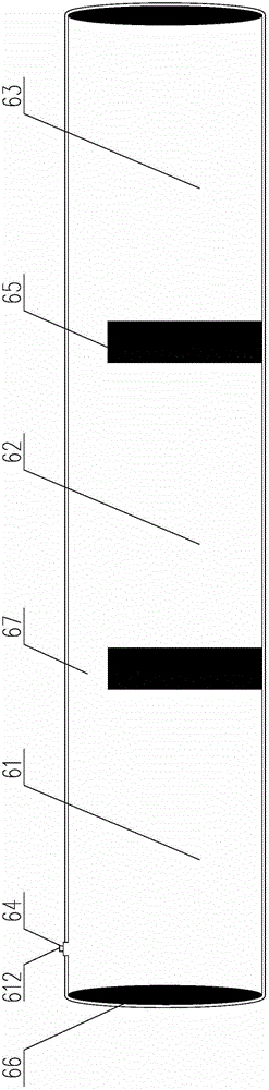
[0025] figure 1 It is a frame steel mesh structure diagram formed by steel mesh and inorganic objects in the first embodiment of the present invention, such as figure 1 As shown, the steel mesh of the frame 5 formed by steel mesh and inorganic objects contains mesh plate 56 and reinforcing rib 57 and connecting plate 58 and side rib 53, and mesh plate 56 and reinforcing rib 57 and connecting plate 58 and side rib 53 form The overall structure of interaction; the steel mesh reinforcement rib 57 is pressed with rows of bending lines 59 in the vertical direction; the steel mesh is determined by the bending lines 59 to make the frame bottom surface 51, the chord edge b2, the frame side wall 531 and the side wall 532, and the frame Top surface 54 and frame top surface 55 length.

[0026] figure 2 It is a converted cross-sectional view of the frame steel mesh formed by the steel...


PUM

PropertyMeasurementUnit
widthaaaaaaaaaa

Abstract

The invention provides a cast-in-place hollow floor system with holes composed of steel meshes and organic objects. The cast-in-place hollow floor system is composed of a main beam, ribbed beams, an upper frange plate, a lower frange plate and a frame formed by the steel meshes and the organic objects; the main beam is a reinforced concrete composite beam or a structural steel beam; the frame formed by the steel meshes and the organic objects is formed by interaction of the steel meshes and the organic objects; the top surface of the frame, the bottom surface of the frame and the two lateral walls of the lateral faces of the frame are formed by the steel meshes; the top surface of the frame is formed by overlapping the head ends and the tail ends of the steel meshes, and the overlapping amount is smaller than or equal to the area of the top surface of the frame; the organic objects comprise an air sac or a polyphenyl block; the other two lateral walls of the lateral faces of the steel mesh frame are formed by the organic objects, and the organic objects are supported between the top surface of the frame and the bottom surface of the frame to conduct height control over the steel mesh combined frame. The steel meshes and the organic objects are combined, blocking of the other two lateral walls of the lateral faces of the frame and supporting of the inner hollow height between the top surface of the frame and the bottom surface of the frame are effectively achieved, and the cast-in-place hollow floor system is easily obtained.

Description

technical field [0001] The invention relates to a cast-in-place hollow floor with holes formed by non-centering filler components, in particular to a cast-in-place hollow floor with holes formed by combining steel mesh and organic objects. Background technique [0002] At present, in the technical field of cast-in-place reinforced concrete hollow floors, fully-sealed filler components are usually used to form holes and form hollow floors, such as ZL200410082381.9 "a hollow small ribbed floor" declared by the inventor, which uses thin-walled The filling body of the box body is buried in the small dense ribbed floor to form a hollow layer with a "T-shaped" stress section, which solves the problem of smooth roof of the small dense ribbed hollow floor with a "T-shaped" stressed section. However, there is no designed stress reinforcement between the bottom of the thin-walled box filling body and the hollow floor formwork, and a layer of crack-resistant steel wire mesh must be add...

Claims


Application Information

Patent Timeline
Patent Type & Authority Applications(China)
IPC IPC(8): E04B5/36
Inventor 王本淼王海崴沈洋
Owner 王本淼
Why Eureka
Try Eureka