Intensive coarse and fine double-layered filtering and chip removing device for cutting fluid

A double-layer filter and chip removal device technology, applied in the direction of filter separation, filter circuit, separation method, etc., can solve the problems of increasing bacterial reproduction, cutting fluid deterioration, increasing production costs and labor costs, etc., to achieve energy saving and cost saving , the effect of prolonging the service life

Active Publication Date: 2014-08-27
ZHANGJIAGANG AAA BEARING
View PDF6 Cites 8 Cited by
  • Summary
  • Abstract
  • Description
  • Claims
  • Application Information

AI Technical Summary

Problems solved by technology

[0002] In the machining industry, the most common way of supplying cutting fluid is stand-alone lubrication and cooling, that is, each stand-alone machine has a set of independent filter cooling circulation system. While the cutting fluid is lubricating and cooling, it also drains chips and machine tools from the machine tool. The oil rushes into the liquid storage tank. After long-term accumulation, a large amount of chips and other solid impurities will be deposited on the bottom of the tank, and there will be oil slick on the liquid surface. The slick oil will prevent the cutting fluid from contacting with the air, which can increase the reproduction of bacteria. Therefore, the service life of the cutting fluid of a single machine is generally only less than one month. Experience shows that whenever the factory is on holiday and the equipment is suspended for a few days. Bacteria in the cutting fluid will grow rapidly, and the cutting fluid will deteriorate and stink. It needs to be replaced with new cutting fluid frequently, which increases production costs and labor costs.

Method used


Image

  • Intensive coarse and fine double-layered filtering and chip removing device for cutting fluid

Examples


Embodiment Construction

[0019] The present invention will be further explained below in conjunction with the accompanying drawings and specific embodiments. It should be understood that the following specific embodiments are only used to illustrate the present invention and are not intended to limit the scope of the present invention. It should be noted that the words "front", "rear", "left", "right", "upper" and "lower" used in the following description refer to the directions in the drawings, and the words "inner" and "outer ” refer to directions towards or away from the geometric center of a particular part, respectively.

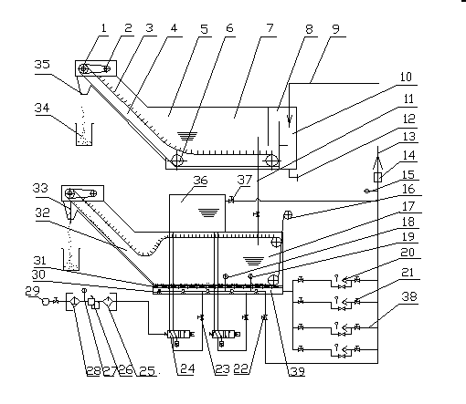
[0020] As shown in the figure, a cutting fluid centralized coarse-fine double-layer filter chip removal device according to the present invention includes a coarse filter water tank 5 and a fine filter water tank 17, and the coarse filter water tank 5 is higher than the fine filter water tank 17, and the machine tool The outflowing cutting fluid flows into the dirty place 10 on...


PUM


Abstract

The invention discloses an intensive coarse and fine double-layered filtering and chip removing device for cutting fluid. The intensive coarse and fine double-layered filtering and chip removing device comprises a coarse filtering water tank and a fine filtering water tank, wherein the cutting fluid flowing out from a machine tool flows into the coarse filtering water tank from a liquid reflowing pipeline; after the cutting fluid is treated by a dirt remaining part and a first sewage treatment device, the cutting fluid in the coarse filtering water tank flows into the fine filtering water tank through a fluid flowing pipe; after being treated by a second sewage treatment device and a non-woven fabric, the cutting fluid is pumped into the machine tool by a water pump so as to be used. According to the intensive coarse and fine double-layered filtering and chip removing device for the cutting fluid, the cutting fluid on all production equipment of a workshop is collected together to be subjected to coarse and fine double-layered filtering and chip removal; clean fluid is intensively filtered and conveyed to each working point to be circularly utilized; the cutting fluid is not easy to go bad and the utilization period of the cutting fluid is prolonged; the intensive coarse and fine double-layered filtering and chip removing device has a beautifying effect on a field working environment, and energy and the cost are saved.

Description

technical field [0001] The invention belongs to a cutting fluid processing device for machining, and in particular relates to a cutting fluid centralized coarse-fine double-layer filter chip removal device. Background technique [0002] In the machining industry, the most common way of supplying cutting fluid is stand-alone lubrication and cooling, that is, each stand-alone machine has a set of independent filter cooling circulation system. While the cutting fluid is lubricating and cooling, it also drains chips and machine tools from the machine tool. The oil rushes into the liquid storage tank. After long-term accumulation, a large amount of chips and other solid impurities will be deposited on the bottom of the tank, and there will be oil slick on the liquid surface. The slick oil will prevent the cutting fluid from contacting with the air, which can increase the reproduction of bacteria. Therefore, the service life of the cutting fluid of a single machine is generall...

Claims


Application Information

Patent Timeline
Patent Type & Authority Applications(China)
IPC IPC(8): B01D36/02
Inventor 顾新忠曹国元陈伟周良良
Owner ZHANGJIAGANG AAA BEARING
Why Eureka
Try Eureka