
soot blower

A soot blower and soot blowing tube technology, which is applied in the fields of electric power equipment and petrochemicals, can solve problems such as rising costs of enterprises, unfavorable long-term development, and affecting service life, so as to prolong service life, improve soot blowing efficiency, and reduce the impact of high temperature Effect

Inactive Publication Date: 2017-01-25
姜建勇
View PDF5 Cites 0 Cited by
  • Summary
  • Abstract
  • Description
  • Claims
  • Application Information

AI Technical Summary

Problems solved by technology

However, the existing soot blowers are generally installed in the furnace, regardless of whether the soot blowing operation is carried out, they are all in the furnace, and the high temperature inside the furnace will corrode the spray gun of the soot blower or cause high temperature in the long run. Bending will eventually affect the service life and cause the cost of the enterprise to rise, which is not conducive to long-term development, so it needs to be improved

Method used


Image

  • soot blower
  • soot blower

Examples


Embodiment Construction

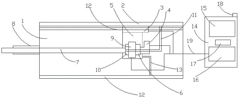
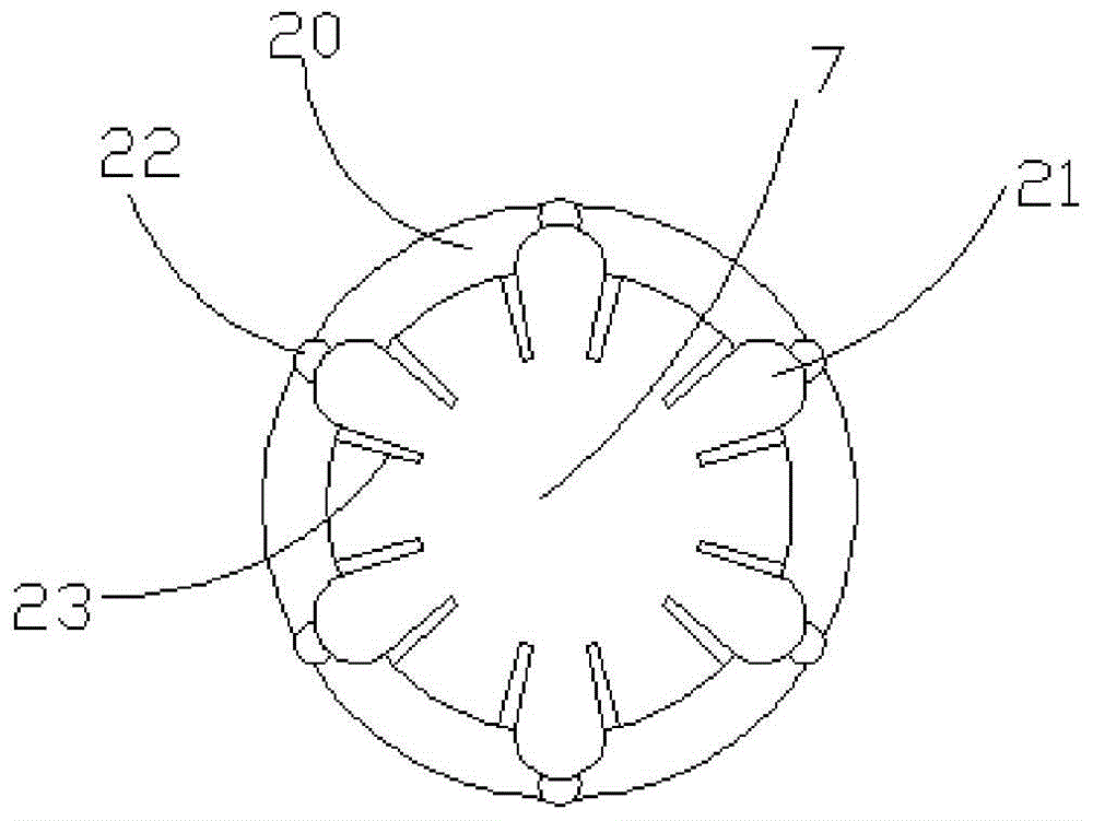
[0018] Such as figure 1 with figure 2 As shown, the present invention relates to a soot blower, which is characterized in that it includes a fixed box 1, a pair of horizontally arranged guide rails 2 are provided on the upper part of the fixed box 1, and a drive motor 3 is provided on the guide rail 2 And the movable table 5 of the rotating motor 4, an input shaft and a double output shaft reducer 6 are provided at the output end of the rotating motor 3, and the output shafts are respectively connected to the soot blowing pipe 7, and the front end of the fixed box 1 A protection tube 8 is provided on the outer wall. The inside of the protection tube 8 allows the soot blowing tube 7 to operate freely back and forth; the two soot blowing tubes 7 are connected to an air pump 10 with a solenoid valve 9 together, and the air pump 10 is connected to an air pipe 11 , The air pipe 11 is arranged on the upper part of the fixed box 1 through the shelf 12; the movable platform 5 is conne...


PUM


Abstract

The invention discloses a soot blower. The soot blower comprises a fixed box, a pair of guide rails which are horizontally arranged are arranged on the upper portion in the fixed box, a mobile table provided with a driving motor and a rotation motor is arranged on the guide rails, an input shaft and a double-output-shaft speed reducer are arranged at the output end of the rotation motor, output shafts of the double-output-shaft speed reducer are connected with soot blowing pipes respectively, a protection pipe is arranged on the outer wall of the front end of the fixed box, and the soot blowing pipes can run freely in a front-and-back mode inside the protection pipe. The two soot blowing pipes are both connected with an air pump with a solenoid valve, the air pump is connected with a gas pipe, and the gas pipe is arranged on the upper portion of the fixed box through a shelf. The mobile table is connected with an integrated circuit, and the integrated circuit is arranged on the lower portion of the fixed box through a shelf. The soot blower can realize telescopic operation control according to actual operation requirements, meanwhile, improve the soot blowing radiation area and the soot blowing efficiency and reduce the use cost of an enterprise.

Description

Technical field [0001] The invention belongs to the technical field of petrochemicals and power equipment, and specifically relates to a soot blower for ash removal and slag removal. Background technique [0002] Heating furnaces in the petrochemical industry, heating furnaces in the power industry, convection tube bundles on boilers, air preheaters, etc., generally use soot blowers to remove ash and slag on their surfaces, which can reduce smoke emissions. It can improve the thermal efficiency of heating furnaces and boilers to achieve the purpose of reducing energy consumption, energy saving and emission reduction. Existing soot blowers are generally installed in the furnace. No matter whether soot blowing is performed or not, they are in the furnace. For a long time, the high temperature inside the furnace will corrode or cause high temperature to the spray gun of the soot blower. Bending will ultimately affect the service life and cause the cost of the enterprise to rise, wh...

Claims


Application Information

Patent Timeline
Patent Type & Authority Patents(China)
IPC IPC(8): F23J3/02F23J1/00
Inventor 姜建勇
Owner 姜建勇
Learn More