
A portable photovoltaic module monitoring terminal

A technology of photovoltaic modules and monitoring terminals, applied in the monitoring of photovoltaic systems, photovoltaic modules, photovoltaic power generation, etc., can solve problems such as power detection, achieve reliable and accurate monitoring data, reduce equipment costs, and facilitate access.

Active Publication Date: 2016-05-11
STATE GRID YANCHENG POWER SUPPLY +4
View PDF5 Cites 0 Cited by
  • Summary
  • Abstract
  • Description
  • Claims
  • Application Information

AI Technical Summary

Problems solved by technology

[0005] The purpose of the present invention is to provide a portable photovoltaic module monitoring terminal, which provides convenient real-time monitoring equipment for photovoltaic module parameters and environmental meteorological parameters, and conveniently solves the technical problems of power detection during the construction and operation of photovoltaic power stations

Method used

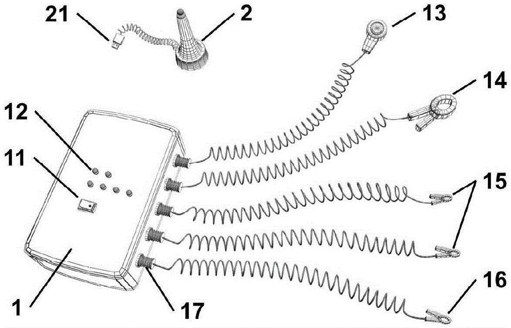
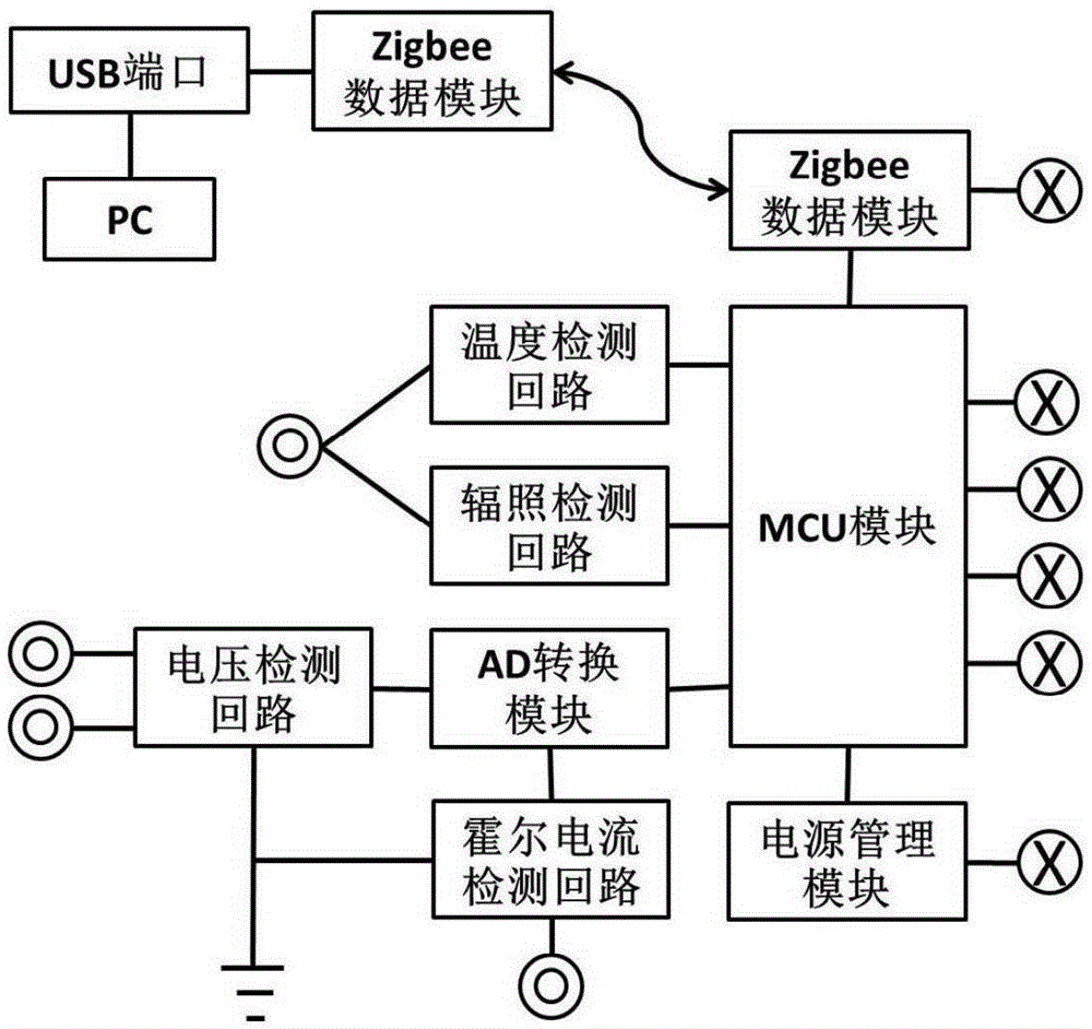
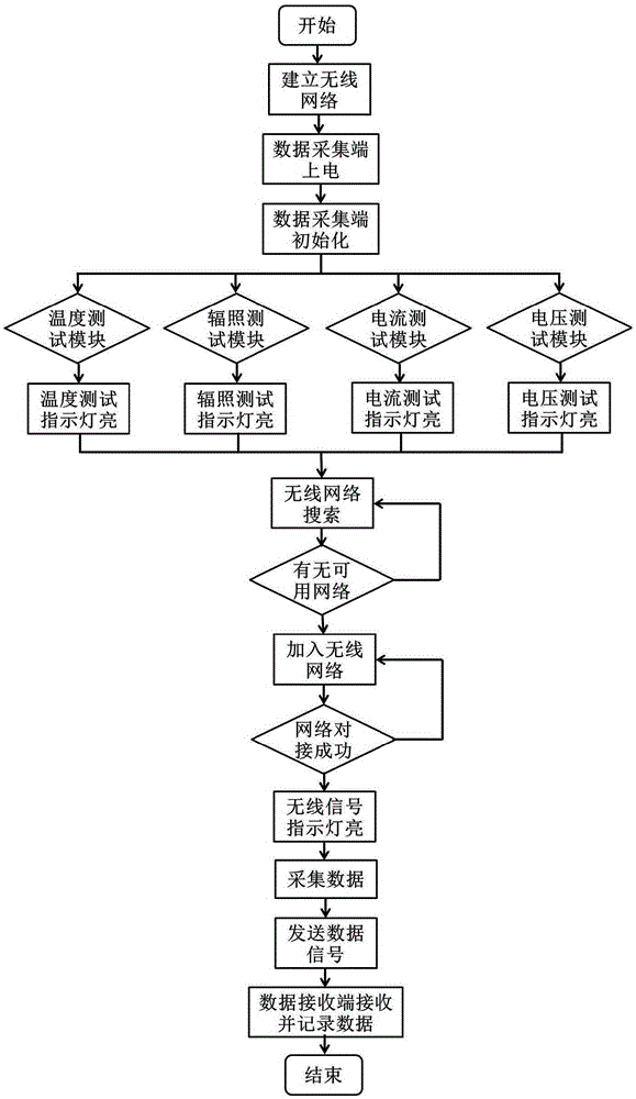

Image

  • A portable photovoltaic module monitoring terminal
  • A portable photovoltaic module monitoring terminal
  • A portable photovoltaic module monitoring terminal

Examples


Embodiment 1

[0025] Before the establishment of the power station, it is necessary to monitor the environmental parameters of the site selection of the power station, including all-weather records of the solar radiation and temperature changes of the photovoltaic module erection, and provide data reference for the design of the power station.

[0026] Use the portable photovoltaic module monitoring terminal of the present invention to monitor environmental parameters, and refer to the operation process image 3 shown. Connect the data receiving end (2) of the portable photovoltaic module monitoring end to the PC, start up the device, and establish a regional Zigbee communication network through the CC2530 module. After determining the possible installation location of the photovoltaic module, the data acquisition terminal (1) is connected to the temperature and radiation sensor (13), without connecting the ground wire. Set up the instrument on site to ensure that the photosensitive elemen...

Embodiment 2

[0031] During the operation of the power station, in order to detect the failure of the photovoltaic module or maintain the normal operation of the power station, the portable photovoltaic module monitoring terminal of the present invention can be used to monitor the current, voltage and surrounding environment parameters of the photovoltaic module.

[0032] Operating procedure reference image 3 , connect the data receiving end (2) of the monitoring end of the portable photovoltaic module to the PC, start and run the device, and pass through the Zigbee communication network in the CC2530 module area.

[0033] The data acquisition end (1) is connected with a temperature and radiation sensor (13), a Hall current clamp (14), a voltage test wire (15) and a ground wire (16). Set up the instrument so that the photosensitive element of the sensor is placed horizontally, the Hall current clamp is clamped into one pole of the photovoltaic module, the voltage test wiring is tapped to t...


PUM


Abstract

The invention discloses a portable photovoltaic assembly monitoring end, and pertains to the technical field of power detection. The portable photovoltaic assembly monitoring end comprises a data acquisition end (1) and a data receiving end (2). The data acquisition end (1) comprises a host box and test wires. A power management module, a MCU module, a Zigbee data module and a temperature, irradiation, Hall current and voltage detection module are integrated into an internal circuit. Each test wire and the ground wire are connected externally through plug and unplug interfaces. The portable photovoltaic assembly monitoring end of the invention assumes the long-periodic photovoltaic assembly real-time monitoring task, the data acquisition end (1) is connected with the photovoltaic assembly and used to acquire the temperature, irradiation, Hall current and voltage data, and by establishing a Zigbee communication network with the data receiving end (2), the data is transmitted to a PC to complete data recording and processing.

Description

technical field [0001] The invention relates to a portable photovoltaic component monitoring terminal, which belongs to the technical field of electric power detection. Background technique [0002] Solar energy is a new type of green energy, which is inexhaustible, clean and non-polluting. Its development and utilization is an inevitable trend in the development of current energy technology. It is of great significance to solve the energy shortage and reduce the pressure of environmental pollution. Among them, the realization of solar photovoltaic utilization is the most ideal way of clean energy utilization, which can overcome the characteristics of low density, high dispersion, instability, and discontinuity of solar energy, and solve key problems such as solar energy enrichment, transfer, and application. Therefore, photovoltaic power generation is the common future energy dream of mankind. [0003] In the existing technology, the development of photovoltaic power plant...

Claims


Application Information

Patent Timeline
Patent Type & Authority Patents(China)
IPC IPC(8): H02S50/10
CPCY02E10/50
Inventor 张怡
Owner STATE GRID YANCHENG POWER SUPPLY
Learn More