Multiple-point fume temperature monitoring device for power station boiler flue and realizing method of device

A technology for power plant boilers and monitoring devices, applied in measuring devices, thermometers, measuring heat, etc., can solve the problems of difficult measurement technology, limited installation extension length of measuring devices, unsuitable for high-temperature flue gas temperature deviation of power plant boilers, etc. Improvement and reliability of measurement results

Active Publication Date: 2014-08-13
SHANGHAI WANGTE ENERGY RESOURCE SICENCE & TECH
View PDF5 Cites 2 Cited by
  • Summary
  • Abstract
  • Description
  • Claims
  • Application Information

AI Technical Summary

Problems solved by technology

However, this technology has the following defects: 1. The object measured by this technology is the metal wall temperature, not the flue gas temperature; 2. The installation extension length of the measuring device is limited, and the flue gas temperature of the horizontal flue of a large power plant boiler with a height of more than 10 meters is limited. Measuring with a certain degree of technical difficulty
However, the disadvantages of this technology are: 1. This technical device is not suitable for large-capacity power plant boilers, but more suitable for waste heat boilers; 2. This technology is a general-purpose device and is not suitable for testing the deviation of flue gas temperature in high-temperature flue of power plant boilers; 3. , the test device needs to be combined with the application method

Method used


Image

  • Multiple-point fume temperature monitoring device for power station boiler flue and realizing method of device
  • Multiple-point fume temperature monitoring device for power station boiler flue and realizing method of device
  • Multiple-point fume temperature monitoring device for power station boiler flue and realizing method of device

Examples


Embodiment 1

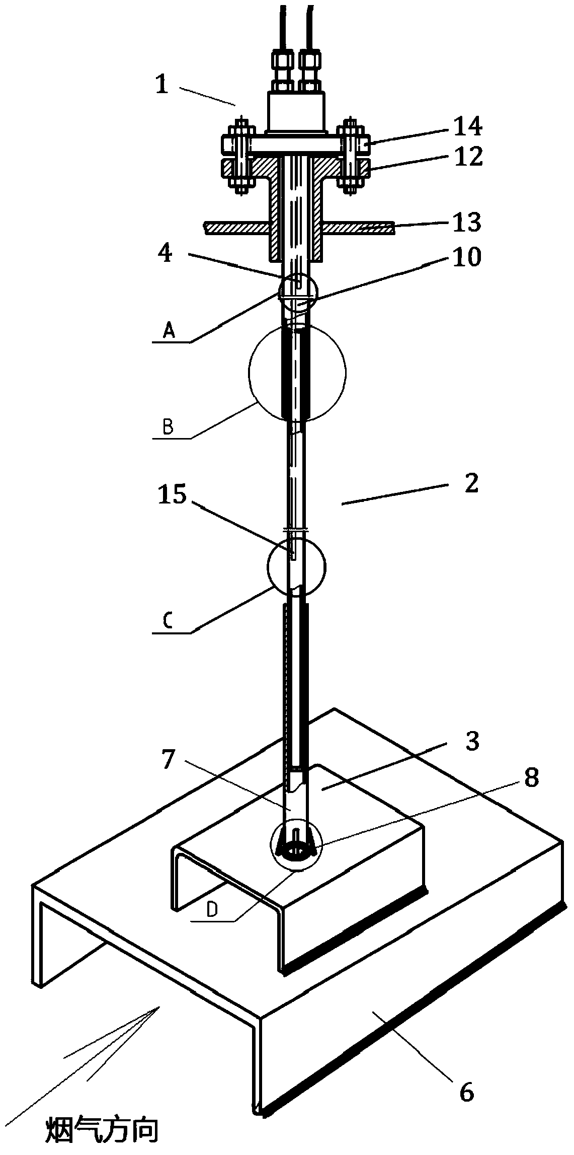
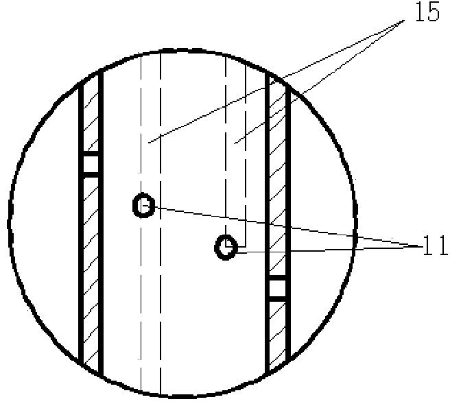
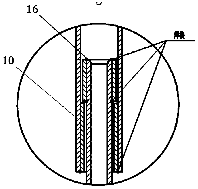
[0028] like figure 1 As shown in -4, this embodiment includes from top to bottom: a base part 1, a telescopic mechanism 2, an anti-vibration mechanism 3, and a plurality of measuring point mechanisms 4 located inside the base part 1 and the telescopic mechanism 2, wherein: the base Part 1 is fixedly installed on the top of the horizontal flue and fixedly connected to one end of the telescopic mechanism 2. The anti-vibration mechanism 3 is fixedly installed on the bottom of the horizontal flue and connected to the other end of the telescopic mechanism 2. The telescopic mechanism 2 is vertically installed at the level of the boiler. In the flue and parallel to the furnace tube 5.

[0029] The anti-vibration mechanism 3 includes: a hollow fixed seat 6 and an anti-vibration tube 7 vertically arranged on the fixed seat 6, wherein: the anti-vibration tube 7 is in contact with the outer wall of the telescopic mechanism 2, and the hollow of the fixed seat 6 The penetration direction ...


PUM


Abstract

The invention discloses a multiple-point fume temperature monitoring device for a power station boiler flue and a realizing method of the device. The device comprises a foundation bed part, a flexible mechanism, a shake-stopping mechanism and measuring point mechanisms arranged inside the foundation bed part and the flexible mechanism, wherein the foundation bed part is fixedly arranged on the top of a horizontal flue and fixedly connected with one end of the flexible mechanism; the shake-stopping mechanism is fixedly arranged on the bottom of the horizontal flue and sleeved with the other end of the flexible mechanism; the flexible mechanism is vertically arranged in the horizontal flue and parallel to a boiler tube. The multiple-point fume temperature monitoring device disclosed by the invention is convenient to install and reliable in measuring result, capable of carrying out temperature monitoring on fume at any height within a range of 800 DEG C-1000 DEG C under a fume speed of 10m/s or higher. Besides, by virtue of the shake-stopping device and anti-abrasion devices with special structures, the multiple-point fume temperature monitoring device disclosed by the invention greatly improves practicability and prolongs service life in comparison with an existing temperature measuring mechanism.

Description

technical field [0001] The present invention relates to a device and method for monitoring the flue gas temperature of a high-temperature flue of a large-scale power plant boiler, specifically a device and method suitable for flue gas flow rates greater than 10m / s, flue gas temperatures of 800°C-1000°C, and flue heights exceeding 10m. The utility boiler flue multi-point flue temperature monitoring device and its implementation method, by combining the limited temperature measuring devices arranged at multiple points along the high-temperature flue with a feasible installation method, the flue gas temperature of the flue on the high-temperature heating surface of the boiler The application of the measured technology is realized. Background technique [0002] With the development of power plant boiler units in the direction of high parameters and large capacity, the safety and reliability of unit operation have become prominent issues. The horizontal flue of flue gas at the o...

Claims


Application Information

Patent Timeline
Patent Type & Authority Applications(China)
IPC IPC(8): G01K1/14
Inventor 王衡宋平魏新华王孟浩
Owner SHANGHAI WANGTE ENERGY RESOURCE SICENCE & TECH
Why Eureka
Try Eureka