
Bullet type flow stabilizer

A technology of flow stabilizer and warhead, which is used in instruments, measurement of flow/mass flow, liquid/fluid solid measurement, etc., can solve problems such as inability to accurately measure fluid flow rate, increase in fluid pulsation amplitude, and impact on data accuracy, and achieve structural Novel, improved accuracy, and the effect of accurately measuring fluid flow rate

Active Publication Date: 2014-08-13
WEIHAI PLOUMETER
View PDF7 Cites 11 Cited by
  • Summary
  • Abstract
  • Description
  • Claims
  • Application Information

AI Technical Summary

Problems solved by technology

[0002] At present, in the measurement of heat meters and water flow, it is mainly realized by placing one or more pairs of ultrasonic transducers at both ends of the pipe under test. The flow velocity of the fluid is calculated by obtaining the forward and reverse propagation velocity difference of the sound wave, and then the flow rate is calculated by the integral formula integrated in the PCB board chip. The above is an ideal situation for a stable fluid. The complex situation at the front end, such as the influence of elbows, variable diameters, valves, filters, etc., makes it difficult to obtain a relatively stable ideal fluid flowing through the flowmeter. Unstable fluid affects the accuracy of measured data
In order to eliminate the influence and obtain a relatively stable fluid, some of the flowmeters are installed with a straight-type flow stabilizer at the inlet, but due to the influence of the length of the meter body, the straight-type flow stabilizer can only be made very short, so the The effect of stabilizing the flow is also very small; in some measuring pipes, the two ends of the stabilizing pipe body are respectively equipped with reflector bases, and the reflector bases are equipped with reflector brackets, and the reflectors are installed on the reflector frame and reflector brackets. The center of the mirror base is in a tilted state. The upper end of the mirror frame is connected to the upper end of the mirror bracket, and the lower end is connected to the lower end of the mirror bracket. Under the reaction, the flow velocity of the fluid is calculated by measuring the forward and reverse propagation velocity difference of the sound wave through one or more pairs of ultrasonic transducers. In the steady flow cavity, the water flow impacts the mirror frame and causes the ultrasonic reflection surface to vibrate, resulting in an increase in the pulsation amplitude of the fluid, which makes it impossible to accurately measure the flow velocity of the fluid

Method used


Image

  • Bullet type flow stabilizer
  • Bullet type flow stabilizer
  • Bullet type flow stabilizer

Examples


Embodiment 1

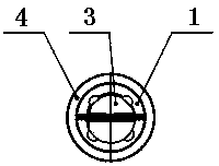
[0025] Embodiment 1: as attached figure 1 , 2 , Shown in 3, a bullet-type current stabilizer is provided with a steady flow pipe body 1, a reflector frame 2, a reflector 3 and a reflection chamber body 4, and the two ends of the flow stabilization pipe body 1 are respectively provided with a reflection chamber pipe body 4, the reflecting cavity tube body 4 is provided with a reflector frame 2, the center line of the reflector frame 2 intersects with the center line of the steady flow tube body 1, and the reflector frame 2 is connected to the reflector cavity through the reflector bracket 5 The pipe body 4 is fixedly connected, and a reflector 3 is installed on one side of the reflector frame 2, and the two reflectors 3 are opposite, and it is characterized in that the other side of the reflector frame 2 is provided with a bullet-shaped fluid 6, and the bullet-shaped stabilizer The bottom end of the fluid 6 is an inclined plane, and the bullet-shaped stabilizing fluid 6 is fi...

Embodiment 2

[0026] Embodiment 2: as attached figure 1 , 6 , Shown in 7, a bullet type current stabilizer is provided with a steady flow tube body 1, a reflector frame 2, a reflector 3 and a reflective cavity tube body 4, and the two ends of the stable flow tube body 1 are respectively provided with a reflective cavity tube body 4, the reflecting cavity tube body 4 is provided with a reflector frame 2, the center line of the reflector frame 2 intersects with the center line of the steady flow tube body 1, and the reflector frame 2 is connected to the reflector cavity through the reflector bracket 5 The pipe body 4 is fixedly connected, and a reflector 3 is installed on one side of the reflector frame 2, and the two reflectors 3 are opposite, and it is characterized in that the other side of the reflector frame 2 is provided with a bullet-shaped fluid 6, and the bullet-shaped stabilizer The bottom end of the fluid 6 is an inclined plane, and the bullet-shaped stabilizing fluid 6 is fixedl...

Embodiment 3

[0027] Embodiment 3: as attached figure 1 , 2, 3, 4, and 5, a bullet-type current stabilizer is provided with a steady flow pipe body 1, a reflector frame 2, a reflector 3 and a reflection chamber body 4, and the two ends of the steady flow pipe body 1 are respectively provided with There is a reflective cavity body 4, the reflective cavity body 4 is provided with a reflector frame 2, the center line of the reflector frame 2 intersects the center line of the steady flow tube body 1, and the reflector frame 2 passes through the reflector bracket 5 is fixedly connected with the reflecting cavity tube body 4, and a reflecting mirror 3 is installed on one side of the reflecting mirror frame 2, and the two reflecting mirrors 3 are opposite, and it is characterized in that the other side of the reflecting mirror frame 2 is provided with a bullet-shaped steady fluid 6, so The bottom end of the bullet-shaped stabilizing fluid 6 is an inclined plane, and the bullet-shaped stabilizing...


PUM


Abstract

The invention discloses a bullet type flow stabilizer which is provided with a flow stabilizing pipe body, a reflecting mirror frame, a reflecting mirror and a reflecting cavity pipe body. The bullet type flow stabilizer is characterized in that a bullet-shaped flow stabilizing body is arranged on the other face of the reflecting mirror frame, the bottom end of the bullet-shaped flow stabilizing body is an oblique face, the bullet-shaped flow stabilizing body is fixedly connected with the other face of the reflecting mirror frame through the oblique face, so that the backs of bullet heads of the bullet-shaped flow stabilizing body are against the flow stabilizing pipe body respectively, the center line of the bullet-shaped flow stabilizing body and the center line of the flow stabilizing pipe body are matched, vibration of an ultrasonic wave reflecting face caused by water flow impacting is greatly lowered, meanwhile, fluid pulsation magnitude is lowered, fluctuant fluid forms relatively-stable fluid in the flow stabilizing pipe through the bullet-shaped flow stabilizing body, namely a Reynolds number Re is lowered to be close to 2300, at the time, ultrasonic wave energy is transmitted in fluid with a relatively-stable speed mean value and is not interfered by external changing factors, and accordingly fluid flow speed can be measured accurately.

Description

technical field [0001] The invention relates to a fluid measuring instrument, in particular to a bullet type flow stabilizer. Background technique [0002] At present, in the measurement of heat meters and water flow, it is mainly realized by placing one or more pairs of ultrasonic transducers at both ends of the pipe under test. The flow velocity of the fluid is calculated by obtaining the forward and reverse propagation velocity difference of the sound wave, and then the flow rate is calculated by the integral formula integrated in the PCB board chip. The above is an ideal situation for a stable fluid. The complex situation at the front end, such as the influence of elbows, variable diameters, valves, filters, etc., makes it difficult to obtain a relatively stable ideal fluid flowing through the flowmeter. Unstable fluid affects the accuracy of the measured data. In order to eliminate the influence and obtain a relatively stable fluid, some of the flowmeters are installe...

Claims


Application Information

Patent Timeline
Patent Type & Authority Applications(China)
IPC IPC(8): G01F1/66
Inventor 付涛徐军门建青
Owner WEIHAI PLOUMETER
Learn More