Electro-hydraulic position servo driver and its driving method based on dsp

A technology of electro-hydraulic position servo and driving method, which is applied in the direction of fluid pressure actuation device, fluid pressure actuation system components, mechanical equipment, etc. The effect of expanding the scope of application and reducing the burden

Active Publication Date: 2016-04-20
敬科(深圳)机器人科技有限公司
View PDF5 Cites 0 Cited by
  • Summary
  • Abstract
  • Description
  • Claims
  • Application Information

AI Technical Summary

Problems solved by technology

[0004] The purpose of the present invention is to solve the non-linear and uncertain links in the system of the existing digital electro-hydraulic position servo driver in the process of electro-hydraulic valve control. Servo high-precision control requirements, providing a DSP-based electro-hydraulic position servo driver and driving method

Method used


Image

  • Electro-hydraulic position servo driver and its driving method based on dsp
  • Electro-hydraulic position servo driver and its driving method based on dsp
  • Electro-hydraulic position servo driver and its driving method based on dsp

Examples


specific Embodiment approach 1

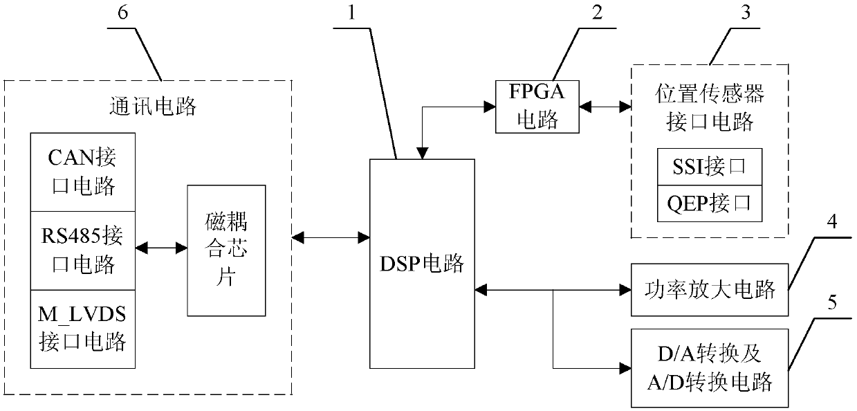
[0028] Specific implementation mode one: combine figure 1 Describe this embodiment, the DSP-based electro-hydraulic position servo driver described in this embodiment includes DSP circuit 1, FPGA circuit 2, position sensor interface circuit 3, power amplifier circuit 4, AD conversion and DA conversion circuit 5 and communication circuit 6 The communication circuit 6 is used to realize the data transmission between the DSP circuit 1 and the upper computer or the control bus; the position sensor interface circuit 3 is used to send the position signal of the differential sensor to the FPGA circuit 2; After processing, it is sent to DSP circuit 1; power amplifier circuit 4 is used to amplify the control quantity sent by DSP circuit 1, and then drives the electro-hydraulic valve; AD conversion and DA conversion circuit 5 is used to convert the analog signal sent from outside After being converted into a digital signal, it is sent to the DSP circuit 1, or the digital control signal ...

specific Embodiment approach 2

[0032] Embodiment 2: This embodiment is a further limitation of the DSP-based electro-hydraulic position servo driver described in Embodiment 1. In this embodiment, the DSP circuit 1 is embedded with a self-calibration module implemented by software. Includes the following units:

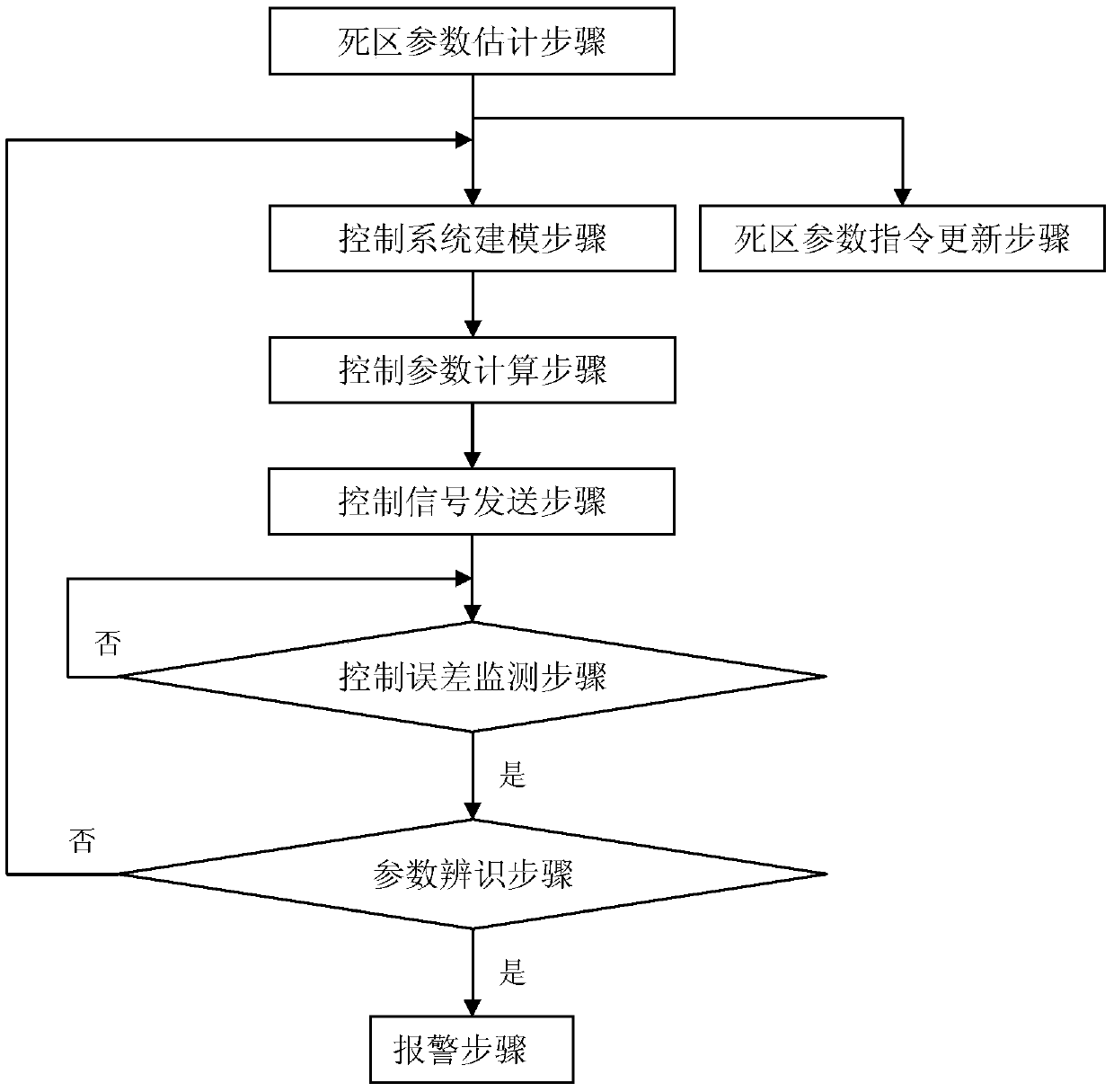
[0033] Dead zone parameter estimation unit: every time t, measure the dead zone width of the system, and start the dead zone parameter updating unit and the control system modeling unit at the same time after the end of the unit;

[0034] Dead zone parameter command update unit: send the measured dead zone width as a new dead zone parameter command to the power amplifier circuit 4;

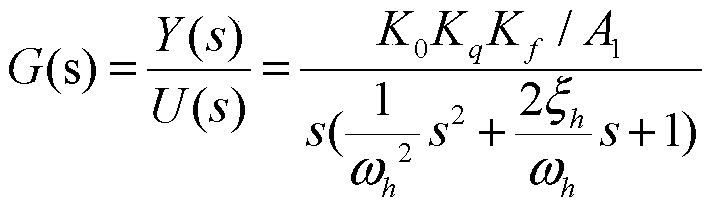
[0035] Control system modeling unit: establish the open-loop transfer function of the proportional valve position control system, and start the control parameter calculation unit after the unit ends;

[0036] Control parameter calculation unit: calculate system control parameters according to the open-loop transfer fun...

specific Embodiment approach 3

[0042] Specific Embodiment 3: This embodiment is a further limitation of the DSP-based electro-hydraulic position servo driver described in Embodiment 2. In this embodiment, the control system modeling unit establishes the open loop of the proportional valve position control system For the transfer function, the initial open-loop transfer function is obtained by calculating the preset system parameters, and the open-loop transfer function in the cycle process is obtained by calculating the identification parameters.


PUM


Abstract

The invention provides a DSP (Digital Signal Processor) based electro-hydraulic position servo driver and control method and relates to an electro-hydraulic position servo driving technology. The DSP based electro-hydraulic position servo driver and control method aims at solving the problems that only linear controllers such as PID (Proportion Integration Differentiation) linear controllers are adopted in the nonlinearity and uncertainty links of systems in the existing digital electro-hydraulic position servo drivers and accordingly the high accuracy control cannot be achieved. A floating-point type DSP is utilized as a main control chip and a floating-point type FPGA (Field Programmable Gate Array) is utilized as an assisted control chip. During initial operation, the parameter design of a controller is performed so as to implement pre-control; a control error is monitored continuously; when the control error is larger than 5%, parameter identification is performed; if the parameter error reaches more than 30%, the controller is redesigned so as to implement self-correction. System dead-zone parameter estimation is performed continuously in the control process so as to implement nonlinear compensation. The control accuracy can reach 0.5 mm. The DSP based electro-hydraulic position servo driver and control method is suitable for high accuracy position servo control of multiple electro-hydraulic valves.

Description

technical field [0001] The invention relates to electro-hydraulic position servo drive technology. Background technique [0002] Electro-hydraulic control system (that is, electro-hydraulic control system) has become the mainstream method of hydraulic control system because of its convenient signal detection, correction and amplification, easy remote control, and close integration with computer technology. Electro-hydraulic control technology has been widely used in the fields of automatic control of various movable equipment in the machine tool industry, construction machinery, industrial robots, plastic processing, geological and mineral exploration, coal mining machinery, metallurgy, and automobile manufacturing machines. Electro-hydraulic servo drive is the most widely used type of electro-hydraulic control system. [0003] The existing electro-hydraulic servo drivers mainly have the following three problems: (1) The control hardware is backward, the control of the anal...

Claims


Application Information

Patent Timeline
Patent Type & Authority Patents(China)
IPC IPC(8): F15B21/08
Inventor 孙敬颋毛琨
Owner 敬科(深圳)机器人科技有限公司
Why Eureka
Try Eureka