Beach cleaning trolley

A cleaning vehicle and cleaning technology, which is applied in the field of beach cleaning vehicles, can solve problems such as damage to garbage conveying devices and oil cylinders, affecting the normal operation of cleaning vehicles, and inability to remove beach garbage, so as to reduce processing accuracy, improve cleaning efficiency, and increase effective The effect of working length

Inactive Publication Date: 2014-08-13
XIAMEN UNIV OF TECH
View PDF7 Cites 24 Cited by
  • Summary
  • Abstract
  • Description
  • Claims
  • Application Information

AI Technical Summary

Problems solved by technology

This structure has the following defects: First, it needs a large space to arrange the oil cylinder to meet the lifting height of the garbage screening and conveying device; second, it may cause damage to the garbage conveying device and the oil cylinder, because the beach is not completely flat, and some There are even raised hard objects under the beach ground. When the head of the garbage conveying device touches a hard object, because the oil cylinder and the garbage conveying device are rigidly connected, both the garbage conveying device and the oil cylinder may be damaged, thereby affecting The normal work of the cleaning car
[0005] The walking device of the existing beach cleaning vehicle is generally tire-type, and the ground pressure of the tire is large, and the tire is easy to sink, and cleaning operations cannot be performed on artificial beaches and swamps; secondly, the turning radius is large and the maneuverability is poor.
[0006] There is still a defect in the existing beach cleaning vehicles, which cannot remove super long and large beach garbage, especially land garbage brought by rivers during floods, such as tree stumps, branches, bamboo poles, animal carcasses, etc. The removal of these garbage needs to be done through Manual or forklift cleaning, the efficiency of manual cleaning is low, and cleaning costs are high if forklifts are used for cleaning

Method used


Image

  • Beach cleaning trolley
  • Beach cleaning trolley
  • Beach cleaning trolley

Examples


Embodiment Construction

[0043] Such as figure 1 As shown, the beach cleaning vehicle disclosed in the present invention includes a crawler chassis 3, a vehicle frame 2, a cleaning roller device 6, a garbage conveying device 4 and a garbage bin assembly 1. The vehicle frame 2 is fixedly connected to the crawler chassis 3, and the cleaning roller device 6 is horizontally connected to the front end of the garbage conveying device 4. Above, the dustbin assembly 1 is hinged to the rear end of the vehicle frame 2 to receive the garbage collected by the garbage conveying device 4 . The vehicle frame 2 is also connected with a rubbish grabbing device 5, which is used to remove elongated rubbish and bulky rubbish that the cleaning roller device 6 cannot collect.

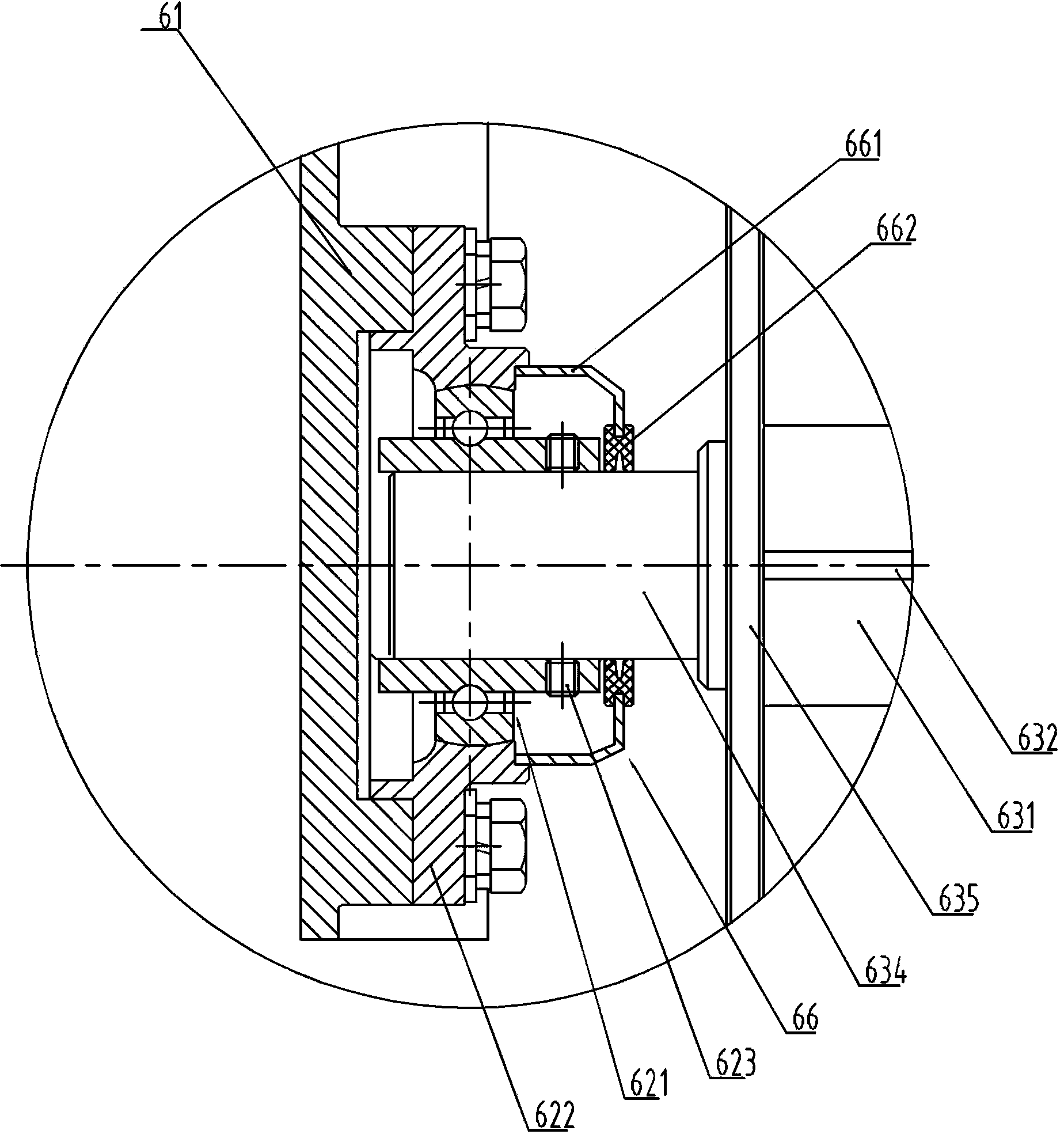
[0044] Such as Figure 2 to Figure 7 As shown, the cleaning roller device 6 includes a cleaning roller fixing frame 61 , a cleaning roller 63 , an outer spherical bearing with seat 62 , a flexible coupling 64 , a hydraulic motor 65 , and a dustpro...


PUM


Abstract

The invention discloses a beach cleaning trolley which comprises a crawler base, a frame, a cleaning roller device, a garbage conveying device and a dustbin component, wherein the frame is connected to the crawler base; the garbage conveying device comprises a garbage conveying mechanism and a flexible lifting mechanism connected between the head and the frame; the rear end of the garbage conveying mechanism is hinged with the frame and can swing up and down around a hinged point; the cleaning roller device comprises a cleaning roller and a cleaning roller fixing rack which are in flexible connection; the cleaning roller fixing rack is hinged to the front end of the garbage conveying mechanism; a garbage gripping device is connected to the frame. Lifting of the flexible lifting mechanism, stretching of the cleaning roller device and stretching of the garbage gripping device are realized by controlling actions of cylinders. The flexible lifting mechanism has the advantages of high throughput capacity and high safety coefficient; the cleaning roller device has the advantages of high cleaning efficiency and long service life; according to the garbage gripping device, the beach cleaning trolley has the advantage that conventional household garbage and large garbage can be cleaned simultaneously.

Description

technical field [0001] The invention relates to a beach cleaning vehicle, in particular to a crawler-type beach cleaning vehicle capable of removing common household garbage and large-size garbage at the same time. Background technique [0002] Most of the nearly 40 coastal cities across the country are developing beach tourism, and beach litter is also increasing day by day, which has become the primary problem bothering the tourism and sanitation departments. At present, some beaches have begun to use machinery to clean up garbage. [0003] In the existing beach cleaning vehicles, one of the key components of the garbage picking device is the sand-discharging roller device, which is connected to the front end of the garbage conveying device. Out to the garbage conveying device, and then screened and conveyed. The length of the sand removal roller is close to the width of the car body. The two ends of the sand removal roller are generally fixed and supported by ordinary d...

Claims


Application Information

Patent Timeline
IPC IPC(8): E01H12/00
Inventor 欧阳联格黄红武葛晓宏周水庭谭璀璨叶玮嵘黄建祥林育从任剑锋
Owner XIAMEN UNIV OF TECH
Why Eureka
Try Eureka