
Vehicle seat slide rail unlocking device and corresponding vehicle seat, vehicle

A vehicle seat and unlocking device technology, which is applied in the vehicle seat slide rail unlocking device, car seat, and vehicle fields, can solve the problems of affecting the unlocking operation force, complex component structure, and large space occupation, so as to improve the operation Stability, high operational stability, soft unlocking process

Active Publication Date: 2017-01-25
GREAT WALL MOTOR CO LTD
View PDF5 Cites 0 Cited by
  • Summary
  • Abstract
  • Description
  • Claims
  • Application Information

AI Technical Summary

Problems solved by technology

This product patent can realize the unlocking of long slide rails, but its component structure is complex and occupies a large space. The power transmission process is complicated when unlocking, and the bending angle of the unlocking cable is too large, which seriously affects the unlocking operation force, which is directly related to the operation force. Affect the convenience and comfort of customers

Method used


Image

  • Vehicle seat slide rail unlocking device and corresponding vehicle seat, vehicle
  • Vehicle seat slide rail unlocking device and corresponding vehicle seat, vehicle
  • Vehicle seat slide rail unlocking device and corresponding vehicle seat, vehicle

Examples


Embodiment 1

[0037] Embodiment 1 A vehicle seat slide rail unlocking device

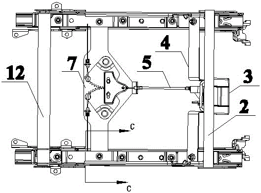
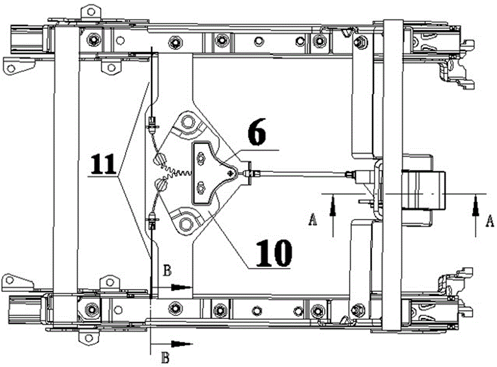
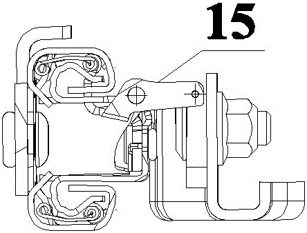
[0038] This embodiment is used to unlock the slide rail of the vehicle seat, and the slide rail of the vehicle seat involved includes a static slide rail 17 (there are two parallel ones) for solid connection with the vehicle body floor, and There are two moving slide rails 16 (there are two parallel ones) that can drive the seat cushion to move back and forth relative to the static slide rails 17. The gap between the dynamic and static slide rails 17 is matched by the extrusion of the ball combination mechanism. In order to prevent the moving slide rails from 16 slips off, and the front and rear ends between the dynamic and static slide rails 17 are respectively provided with a blocking point spacing structure. A slide rail brake hook 15 for locking and unlocking the relative positional relationship between the moving and static slide rails 17 is provided. The brake hook 15 of the slide rail is connected to the ...

Embodiment 2

[0054] Embodiment 2 A car seat

[0055] This embodiment includes a seat slide rail and an unlocking device thereof, which differs from existing vehicle seats only in that the unlocking device is the vehicle seat slide rail unlocking device provided in Embodiment 1.

[0056] The structure of other parts of the present embodiment is identical with the existing vehicle seat.

Embodiment 3

[0057] Embodiment 3 A vehicle

[0058] The vehicle includes a seat, which differs from the existing vehicle seat only in that the seat includes the vehicle seat provided in Embodiment 2.

[0059] The structure of other parts of this embodiment is identical with existing vehicles.


PUM


Abstract

The invention discloses a vehicle seat sliding rail unlocking device which comprises an unlocking buckling hand used for serving as an unlocking motion starting power source and fixed at the front end of a seat. The rear of the unlocking buckling hand is fixedly connected with a front-rear direction driving pull line, the rear end of the driving pull line is fixedly connected with a transmission mechanism, wherein the output end of the transmission mechanism is fixedly connected with a sliding braking hook, and the transmission mechanism can convert forward linear motion of the driving pull line into unlocking rotational motion of the sliding braking hook. The invention further discloses a corresponding vehicle seat and vehicle. According to the vehicle seat sliding rail unlocking device, a toothed plate is driven to rotate through linear motion, the rotation is converted into linear motion, power is finally transmitted to a sliding rail, front-rear adjustment of a cushion is achieved, operation stability is high, and the unlocking process is soft and free of abnormal sound. The vehicle seat sliding rail unlocking device is suitable for various vehicle seats so as to achieve sliding rail unlocking.

Description

technical field [0001] The invention belongs to the field of vehicle components, and relates to an unlocking mechanism for a vehicle seat slide rail, in particular to an unlocking device for a vehicle seat slide rail, a corresponding vehicle seat and a vehicle. Background technique [0002] The slide rail for the vehicle seat is the main functional component of the passenger car seat, and the front and rear movement of the seat cushion is realized by the movement of the slide rail. [0003] Unlocking with a U-shaped handle is an existing manual slide rail unlocking method, which forces the slide rail to unlock by pulling the handle upwards. It is difficult to ensure the parallelism of the U-shaped handle during the manufacturing process; in addition, deformation occurs during transportation, resulting in one high and one low unlocking end prone to unlocking asynchronous problems; also, in the process of vehicle operation or slide rail unlocking adjustment Among them, it is ...

Claims


Application Information

Patent Timeline
Patent Type & Authority Patents(China)
IPC IPC(8): B60N2/08
Inventor 邵希臣韩光明刘志熊培建石广亮郭响陈亚静
Owner GREAT WALL MOTOR CO LTD
Learn More