Conductive member, process cartridge, and electrophotographic apparatus
A conductive member and conductive technology, applied to the equipment of the electric recording process using the charge pattern, the electric recording process using the charge pattern, and the electric recording technique, etc., can solve the problem of charge residue, image density, and the inability to obtain a relaxation and development member Achieve high quality and suppress unevenness due to problems such as sufficient charge time
- Summary
- Abstract
- Description
- Claims
- Application Information
AI Technical Summary
Problems solved by technology
Method used
Image

Examples
experiment example I
[0093] Production and Evaluation of Experimental Example 1 Elastic Roller
[0094]
[0095] (Component (A))
[0096] A linear polydimethylsiloxane in which both terminals of the molecular chain are terminated with dimethylvinylsilyl groups having the viscosity and vinyl equivalent shown in Table 1 was used as component (A).
[0097] [Table 1]
[0098] Table 1
[0099] A-1
Viscosity: 40.0Pa·s, vinyl equivalent: 0.025mmol / g
A-2
Viscosity: 5Pa·s, vinyl equivalent: 0.040mmol / g
A-3
Viscosity: 150Pa·s, vinyl equivalent: 0.017mmol / g
A-4
Viscosity: 300Pa·s, vinyl equivalent: 0.015mmol / g
A-5
Viscosity: 100Pa·s, vinyl equivalent: 0.020mmol / g
A-6
Viscosity: 10Pa·s, vinyl equivalent: 0.033mmol / g
[0100] (Component (B))
[0101] Organopolysiloxanes having the viscosities and vinyl equivalents shown in Table 2 were used as component (B).
[0102] [Table 2]
[0103] Table 2
[0104]
[0105]
[0106] ...
Embodiment 1
[0117]
[0118] First, the materials shown in Table 4 were kneaded with a kneader to produce a kneaded product.
[0119] [Table 4]
[0120] Table 4
[0121] Organopolysiloxane (A-1) as component (A)
100 copies
Organopolysiloxane (B-1) as component (B)
1.3 parts
[0122] Thereafter, D-1 was added as component (D) such that the amount of D-1 was 5 parts relative to 100 parts of the total amount of components (A) and (B) and component (C) shown in Table 5 , followed by dispersion with a two-roll mill. Then, the materials shown in Table 5 were kneaded with a two-roll mill to produce a kneaded product.
[0123] [table 5]
[0124] table 5
[0125]
[0126] The two kneaded products were further kneaded with a planetary mixer. Thus, an uncured conductive silicone rubber mixture is obtained.
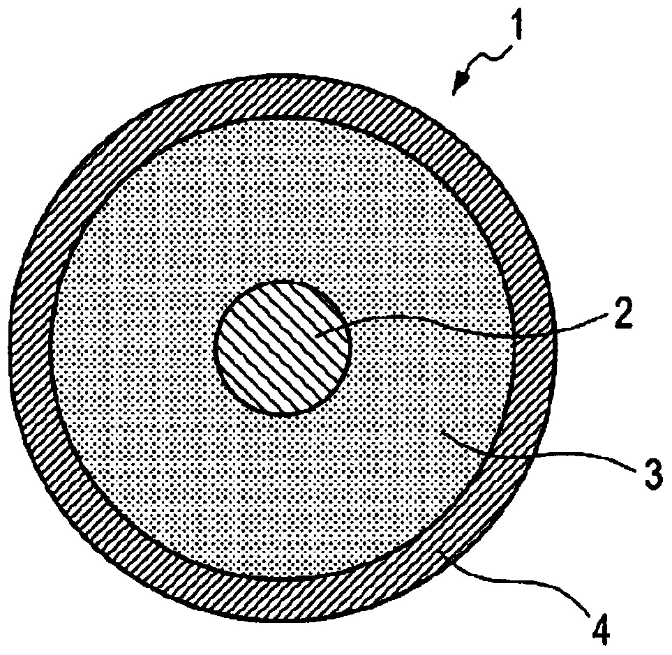
[0127] Next, a mandrel made of stainless steel (SUS304) having a diameter of 6.0 mm was prepared as the mandrel 2 . A primer (trade name: DY35-051, manuf...
Embodiment 2-12
[0138] Elastic rollers of Examples 2-12 were each produced in the same manner as in Example 1, except that Component (A)-Component (E) in Example 1 were changed as shown in Table 6. The same evaluation as in Example 1 was performed.
[0139] Table 6 shows the results.
PUM
| Property | Measurement | Unit |
|---|---|---|
| electrical resistivity | aaaaa | aaaaa |
| thickness | aaaaa | aaaaa |
| diameter | aaaaa | aaaaa |
Abstract
Description
Claims
Application Information
 - R&D
- Intellectual Property
- Life Sciences
- Materials
- Tech Scout
- Unparalleled Data Quality
- Higher Quality Content
- 60% Fewer Hallucinations
Browse by: Latest US Patents, China's latest patents, Technical Efficacy Thesaurus, Application Domain, Technology Topic, Popular Technical Reports.
© 2025 PatSnap. All rights reserved.Legal|Privacy policy|Modern Slavery Act Transparency Statement|Sitemap|About US| Contact US: help@patsnap.com