
Current terminal

A connection terminal and current technology, applied in the direction of conductive connection, circuit, connection, etc., can solve the problems of conductive sheet collision, incomplete contact, upper slider falling, etc., and achieve the effect of stable movement and simple structure

Inactive Publication Date: 2014-08-06
CHENGDU MENDERES ELECTRIC
View PDF11 Cites 1 Cited by
  • Summary
  • Abstract
  • Description
  • Claims
  • Application Information

AI Technical Summary

Problems solved by technology

The main disadvantage of this kind of terminal is that the upper and lower sliders are easy to collide with the conductive sheet during the horizontal sliding process, resulting in poor sliding and inappropriate contact. In severe cases, the terminal will be broken down, and its sliding It is easy to accidentally drop the block on the conductive sheet, which has potential safety hazards, and the structure is also relatively complicated

Method used


Image

  • Current terminal
  • Current terminal
  • Current terminal

Examples


Embodiment Construction

[0019] In order to understand the purpose, technical solutions and beneficial effects of the present invention more clearly, the present invention will be further described below in conjunction with the accompanying drawings, but the protection scope of the present invention is not limited to the following examples.

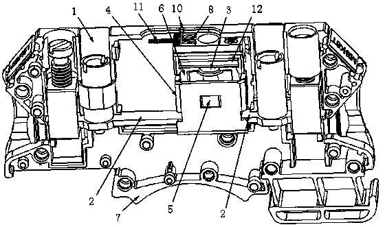
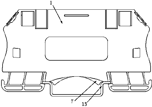
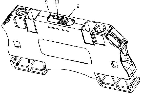
[0020] Such as Figure 1 to Figure 3 As shown, a current connection terminal includes a base body 1, a conductive sheet 2 located in the base body 1, and a current on-off control device. The current on-off control device includes a stay 5 set on a rotating device 3, a crimp 4 and a pressing device 6 located above the guide block; the crimping clamp 4 is connected to the stay 5, and the pressing device 6 is a pressing block; the rotating device 3 is a rotating screw, which is sleeved on the stay 5 Above, when the screw 3 is rotated, the stay 5 is stressed, so that the crimping clamp 4 rises and falls, and clamps or loosens the conductive sheet 2 together with the ...


PUM


Abstract

The invention discloses a current terminal. The current terminal comprises a substrate (1), conducting strips (2) and a current on-off control device. The conducting strips (2) and the current on-off control device are positioned in the substrate (1), and the current on-off control device comprises a bracing strip (5), a wire pressing clamp (4) and a pressing device (6), the bracing strip (5) and the wire pressing clamp (4) sleeve a rotating device (3), and the pressing device (6) is positioned above a guide block. The current on-off control device of the current terminal is simple in structure, stable in operation, large in contact area and low in contact resistance; a rotating screw controls the bracing strip to move up and down to further drive the wire pressing clamp to move up and down, and accordingly stability and reliability in connection of a pressing block and the conducting strip can be controlled; by means of cooperation of an installation guide rail and a stop device (7) in a butterfly clamping structure, quickness and convenience in mounting and demounting can be realized; on or off status, displayed by an internal current on-off indication device (8), of a current loop can be directly seen through an observation window (9).

Description

technical field [0001] The invention belongs to the field of electrical connectors, and in particular relates to a current connection terminal. Background technique [0002] As the degree of industrial automation is getting higher and higher, the requirements of industrial control are becoming more and more strict and precise, and the amount of terminal blocks is gradually increasing, and the scope of use is becoming wider and wider, and there are more and more types. [0003] At present, the most common wiring terminal structure is: including a base body, a conductive sheet arranged in the base body, and a current connecting device. The current connecting device is mainly an upper slider and a lower slider whose relative motion is controlled by a rotating screw, that is, when When the screw is tightened, the upper slider and the lower slider move towards each other, and after being clamped with the conductive sheet, they serve as a bridge for current connection to realize e...

Claims


Application Information

Patent Timeline
Patent Type & Authority Applications(China)
IPC IPC(8): H01R4/38H01R13/629
CPCH01R9/2633
Inventor 李正强任志昊雷毅
Owner CHENGDU MENDERES ELECTRIC
Learn More