Optical navigation device and optical navigation method

A technology of optical navigation and light source, which is applied to the input/output process of instruments, electrical digital data processing, and data processing, etc., can solve the problems of poor navigation effect, inability to adjust the size of comparison blocks, and consumption of resources of optical navigation devices, etc. Achieving good comparison results

Active Publication Date: 2017-10-27
PIXART IMAGING INC
View PDF3 Cites 0 Cited by
  • Summary
  • Abstract
  • Description
  • Claims
  • Application Information

AI Technical Summary

Problems solved by technology

This default comparison block size is fixed and cannot be adjusted
In some cases (for example: poor working surface, out of focus, etc.), the image captured by the image sensor is relatively blurred. If the default comparison block size is too small, the navigation effect will not be as good as that used reader's expectations
However, if the default comparison block size is increased, the comparison will consume too many resources of the optical navigation device

Method used


Image

  • Optical navigation device and optical navigation method
  • Optical navigation device and optical navigation method
  • Optical navigation device and optical navigation method

Examples


Embodiment Construction

[0038] The optical navigation device and the optical navigation method provided by the present invention will be explained through the following examples. However, the embodiments of the present invention are not intended to limit the present invention to be implemented in any environment, application or manner as described in the embodiments. Therefore, the descriptions about the embodiments are only for the purpose of illustrating the present invention, rather than directly limiting the present invention. It should be noted that in the following embodiments and illustrations, elements not directly related to the present invention have been omitted and not shown.

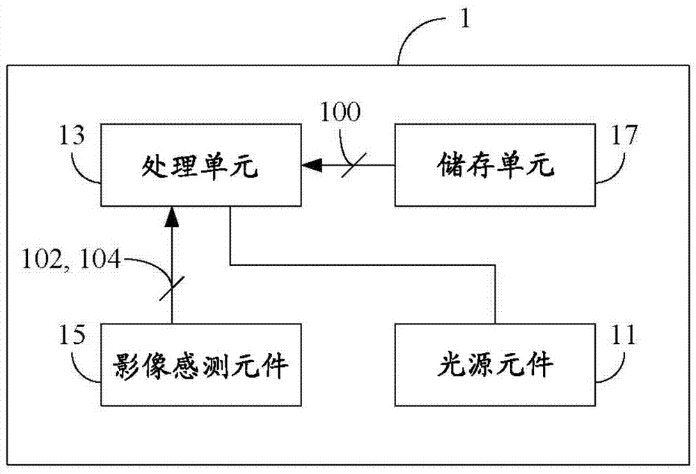
[0039] The first embodiment of the present invention is an optical navigation device 1, the schematic diagram of which is depicted in Figure 1A middle. The optical navigation device 1 includes a light source element 11 , a processing unit 13 , an image sensing element 15 and a storage unit 17 , and the processing...


PUM


Abstract

An optical navigation device and an optical navigation method. The optical navigation device includes a light source element, an image sensing element and a processing unit. The processing unit is electrically connected to the light source element and the image sensing element. The light source element is used to generate a light source. The image sensing element captures a first image at a first time point when the light source is projected onto a reflective surface. The processing unit calculates an image quality parameter related to the first image, and determines a comparison block size between the first image and a second image according to the image quality parameter.

Description

technical field [0001] The present invention relates to an optical navigation device and an optical navigation method; in detail, the present invention relates to an optical navigation device and an optical navigation method capable of dynamically adjusting the comparison block size. Background technique [0002] Computers have become an indispensable necessity in modern life. Most of the existing computer peripherals adopt the mouse as one of the main input devices. When a user operates a computer, he often needs to use the mouse to move the cursor on the screen, or even to click on the required options, applications, etc., so the mouse has become an important bridge between the user and the computer. As a result, various manufacturers have launched mice using various technologies. In recent years, optical navigation devices, such as Optical Finger Mouse (OFM), have been launched on the market. [0003] The optical navigation device uses a light source element to project...

Claims


Application Information

Patent Timeline
Patent Type & Authority Patents(China)
IPC IPC(8): G06F3/033
Inventor 李育儒陈之悠
Owner PIXART IMAGING INC
Why Eureka
Try Eureka