Optical fiber adaptation terminal

A technology of transfer terminal and connection terminal, which is applied in the direction of fiber mechanical structure, etc., can solve the problems of limited operating environment conditions, unfavorable safe operation of substations, and large volume of optical fiber junction boxes, so as to improve engineering quality and fault handling speed and convenience. Test and Troubleshoot, Connectivity Information Intuitive Effects

Inactive Publication Date: 2014-08-06
STATE GRID CORP OF CHINA +1
View PDF3 Cites 0 Cited by
  • Summary
  • Abstract
  • Description
  • Claims
  • Application Information

AI Technical Summary

Problems solved by technology

[0003] 1. Since the optical fiber core of the optical cable and the optical fiber interface need to be welded on site, it not only seriously affects the construction progress of the substation, but also due to the uneven technical level of the on-site technicians and limited operating environment conditions, the quality of the fusion of the optical fiber core and the optical port of the optical fiber distribution box is difficult. Guarantee, affect the quality and stability of optical fiber communication
[0004] 2. The fusion joint between the fiber core and the optical port of the existing optical fiber distribution box is sealed in the box body, and the corresponding information of the fusion connection between the optical fiber core and the optical port is not visible, which affects the smooth development of cable channel troubleshooting and operation and maintenance work
[0005] 3. The existing optical fiber junction box is too large, occupying a large space in the screen cabinet, which is not conducive to the integration of smart devices
[0006] 4. In the existing optical fiber distribution box, multiple optical cables share one box body. When performing a certain channel test or troubleshooting, if you need to observe the splicing situation, you must pull out the entire tray, which may affect other operating channels, which is not conducive to the maintenance of the substation. safe operation
[0007] 5. In the existing optical fiber distribution box, multiple fiber cores share one tray. In order to replace the optical cable without affecting the safe operation of the substation, it is necessary to increase the redundant configuration of the optical fiber tray, and the increased equipment investment

Method used


Image

  • Optical fiber adaptation terminal
  • Optical fiber adaptation terminal
  • Optical fiber adaptation terminal

Examples


Embodiment 1

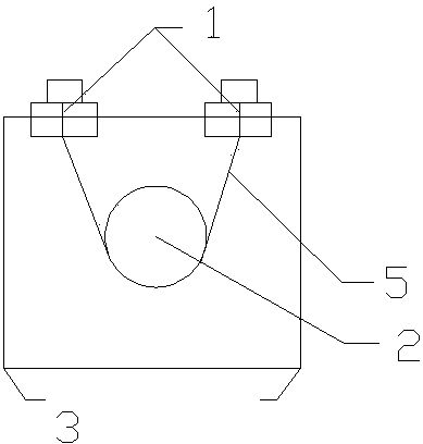
[0024] Embodiment 1: as figure 1 The two optical fiber flanges are arranged on one end surface of the packaging box.

[0025] The two optical fiber flanges are respectively arranged on both sides of the packaging box, specifically designed according to the shape of the packaging box:

Embodiment 2

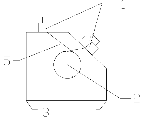
[0026] Embodiment 2: as figure 2 The vertical section of the packaging box is pentagonal, and the two optical fiber flanges are respectively arranged on two adjacent side surfaces of the packaging box.

Embodiment 3

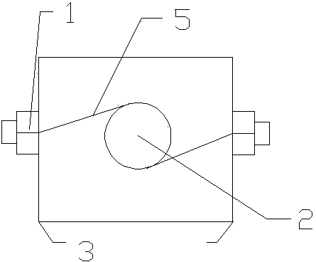
[0027] Embodiment 3: as image 3 The two optical fiber flanges are respectively arranged on two opposite sides of the packaging box.

[0028] The present invention is mainly installed in the intelligent substation protection screen 6 and the intelligent terminal box 4. The specifications of the optical fiber flanges are configured according to the common flange types FC, SC, and ST. Other types can also be flexibly configured according to engineering needs. The three types of flanges Optical fiber transfer terminals can be flexibly installed according to project configuration requirements, among which ST type is mainly used for horizontal installation mode such as Figure 4 As shown, FC and SC types can be flexibly installed vertically according to the internal space of the screen cabinet and the fixing method of optical cables, such as Figure 5 shown.

[0029] The present invention replaces the traditional ODF optical fiber fusion splicing unit with an optical fiber transf...


PUM


Abstract

The invention discloses an optical fiber adaptation terminal. The optical fiber adaptation terminal comprises a connection terminal body, wherein a fixing frame is arranged at the bottom of the body, two optical fiber flanges are arranged on the side face of the body, an optical fiber fixing shaft is arranged in the terminal body, and communicating optical fibers between the two optical fiber flanges are fixed through the optical fiber fixing shaft. The optical fiber adaptation terminal is simple in structure, the packaging mode that optical fiber channels are independently configured according to optical fiber channels is adopted, the packaging mode and the fixing mode of a duplex air switch are adopted as the packaging mode and the fixing mode of the optical fiber adaptation terminal, the size of the optical fiber adaptation terminal is not larger than that of the duplex air switch, not only is the screen cabinet space greatly saved, but also connection between an optical cable and a tail fiber can be clear at a glance, connecting information is very visual, and testing and troubleshooting on the optical fiber channels in the construction and operation and maintenance of a transformer substation are very convenient to perform.

Description

technical field [0001] The invention relates to a transfer terminal, in particular to an optical fiber transfer terminal. Background technique [0002] At present, the construction of smart substations, as an important part of smart grids, is advancing rapidly. However, the fiber channel equipment that constitutes the core of smart substations has not yet produced special equipment that matches the construction of power grid operation and maintenance, and still uses the original communication industry. Equipment or components are very unfavorable to the construction and operation and maintenance of smart substations. In particular, the existing optical fiber distribution boxes in smart substations have the following deficiencies: [0003] 1. Since the optical fiber core of the optical cable and the optical fiber interface need to be welded on site, it not only seriously affects the construction progress of the substation, but also due to the uneven technical level of the o...

Claims


Application Information

Patent Timeline
Patent Type & Authority Applications(China)
IPC IPC(8): G02B6/44
Inventor 宋庭会程悦贤孙明刘丙申于跃
Owner STATE GRID CORP OF CHINA
Why Eureka
Try Eureka