
A phase compensation method for multi-probe array imaging

A phase compensation and multi-probe technology, applied in the field of phase compensation, can solve the problems of increasing hardware costs, errors, and inapplicability of two-dimensional arrays, achieving high-resolution imaging, improving imaging quality, and saving hardware resource costs

Inactive Publication Date: 2016-05-25
CHINA ELECTRONIS TECH INSTR CO LTD
View PDF4 Cites 0 Cited by
  • Summary
  • Abstract
  • Description
  • Claims
  • Application Information

AI Technical Summary

Problems solved by technology

The disadvantage of this method is that it takes a lot of effort to design the array, and a reasonable array design can only reduce the equivalent phase error to a certain extent
[0010] The second is to use the phase compensation method of the metal cylinder or wire introduced in the previous section. This phase compensation method has the following problems: 1. The metal cylinder or wire can only be approximately equivalent to an ideal point target, obviously there is an approximation error, and the metal cylinder Or if the size of the metal wire is too large, the error will be larger, if it is too small, the echo will be easily submerged by noise, so you need to choose a suitable size
2. The compensation method is only applicable to one-dimensional array imaging, not applicable to two-dimensional array
3. Since the compensation method is realized by hardware, it is inevitable to increase the hardware cost and introduce various measurement errors

Method used

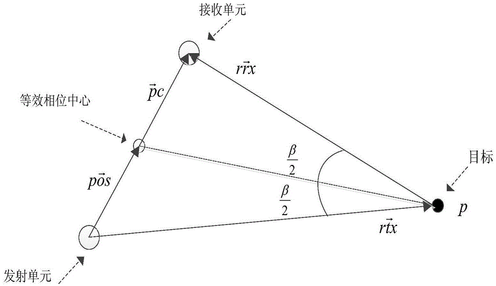
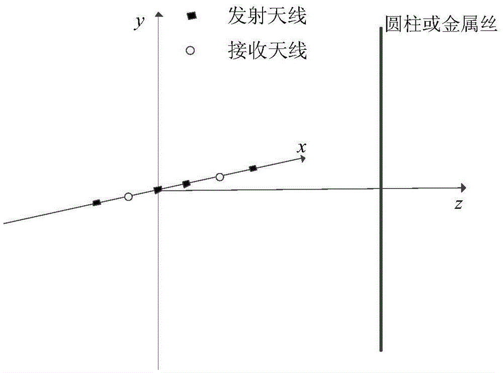

Image

  • A phase compensation method for multi-probe array imaging
  • A phase compensation method for multi-probe array imaging
  • A phase compensation method for multi-probe array imaging

Examples


Embodiment 1

[0032] The purpose of the present invention is to propose a phase compensation method for multi-probe array imaging to reduce the equivalent phase center error of the array and improve the imaging quality in view of the problems existing in the traditional array phase compensation method.

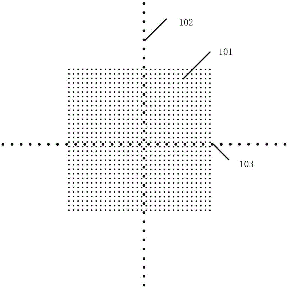
[0033] Such as image 3 as shown, image 3 Among them, 101 is the equivalent phase center, 102 is the transmitting antenna, and 103 is the receiving antenna, assuming that the position of the point target is at (x 0 ,y 0 ), the distance from the multi-probe array is R, when the equivalent phase center array is used for single-station imaging (the receiving and transmitting antennas are all at the equivalent phase center position), the receiving antenna receives the echo signal (regardless of the amplitude) as formula 1:

[0034] S m o - s t a (...

Embodiment 2

[0050] On the basis of the above examples, if Figure 4 As shown, a phase compensation method for multi-probe array imaging includes the following steps:

[0051] Step 1: According to the layout of the multi-probe array, establish a coordinate system to determine the coordinate position of each transmitting antenna and receiving antenna, which is used to calculate the theoretical echo of the point target;

[0052] Step 2: According to the equivalent phase center approximation principle, determine the corresponding relationship between each pair of transmitting and receiving antennas and their corresponding equivalent phase centers, and calculate the coordinates of the equivalent phase center matrix;

[0053] Step 3: Determine the position coordinates of the center point according to the position of the imaging area, and calculate the echo signal S received by the receiving antenna when the multi-probe array performs single-station equivalent imaging mo_sta (n,k);

[0054] St...


PUM


Abstract

The invention provides a phase compensating method used for multi-probe array imaging. The phase compensating method comprises the steps that 1 the coordinate position of each sending antenna and the coordinate position of each receiving antenna are determined; 2 the corresponding relationship between each pair of sending and receiving antennas and a corresponding equivalent phase center of the pair of sending and receiving antennas is determined; 3 echo signals received by the receiving antennas are calculated when a multi-probe array is used for conducting single-station equivalent imaging; 4 echo signals of the receiving antennas are calculated when a real multi-probe array is used for conducting double-state imaging; 5 phase compensating matrixes of the multi-probe array are calculated; 6 sampling signals are multiplied by the phase compensating matrixes Factor of the multi-probe array, and then imaging testing is conducted. By the adoption of the scheme, the imaging quality is improved, and the method has great advantages in the aspects such as high-resolution imaging and hardware resource cost saving. The multi-probe antenna array conducting phase compensating through the method can effectively conduct one-dimensional or two-dimensional or three-dimensional imaging on objects.

Description

technical field [0001] The invention belongs to the technical field of phase compensation, and in particular relates to a phase compensation method for multi-probe array imaging. Background technique [0002] The multi-probe array imaging technology has great potential in imaging. It is composed of multiple transmitting units and receiving units. It adopts the working form of switch control. Each time there is only one pair of transmitting and receiving antennas working, which can effectively suppress the coupling between antennas. The number of virtual array units is far greater than the number of actual antennas, thereby greatly saving the hardware cost and construction difficulty of the array. Range Migration Algorithm (RMA) is a relatively accurate scattering imaging algorithm, which can be applied to multi-probe array scattering imaging. However, due to the approximation of the equivalent phase center when the range migration algorithm is applied to the multi-probe arr...

Claims


Application Information

Patent Timeline
Patent Type & Authority Patents(China)
IPC IPC(8): G01S13/89
CPCG01S7/006G01S13/89
Inventor 胡大海周杨杜刘革常庆功王亚海
Owner CHINA ELECTRONIS TECH INSTR CO LTD
Learn More