Control mechanism for clutch and control method of control mechanism

A control mechanism and clutch technology, which is applied to clutches, mechanical drive clutches, mechanical equipment, etc., can solve the problems of vehicle power loss, poor driving comfort, and poor shifting smoothness, so as to save design and modification costs and improve shifting performance. Ride comfort and the effect of improving vehicle economy

Inactive Publication Date: 2014-08-06
XIHUA UNIV
View PDF5 Cites 5 Cited by
  • Summary
  • Abstract
  • Description
  • Claims
  • Application Information

AI Technical Summary

Problems solved by technology

[0005] 1. If the combination is too fast, it may cause the vehicle to vibrate, or even cause the engine speed to drop rapidly or even stop due to a sudden increase in load, which is often called "suffocating" flameout
During driving, when switching gears, due to the separation of the clutch and gear switching, there is a speed difference between the speed of the transmission shaft and the speed of the engine. Therefore, if the combination is too fast, the body will vibrate due to the existence of the speed difference. That is commonly referred to as "jumping" front and rear, resulting in poor driving comfort
[0006] 2. If the combination process is too slow, it will lead to the loss of vehicle power, the vehicle speed drops too much, and the smoothness of shifting is not good
Therefore, the power transmission system of this kind of mechanical manual transmission often gives people the feeling that it is difficult to control. Frequent clutch operations make the ankles very tired, which makes many people feel "fear".

Method used


Image

  • Control mechanism for clutch and control method of control mechanism
  • Control mechanism for clutch and control method of control mechanism
  • Control mechanism for clutch and control method of control mechanism

Examples


Embodiment Construction

[0022] The following will be described in conjunction with the accompanying drawings and a specific embodiment.

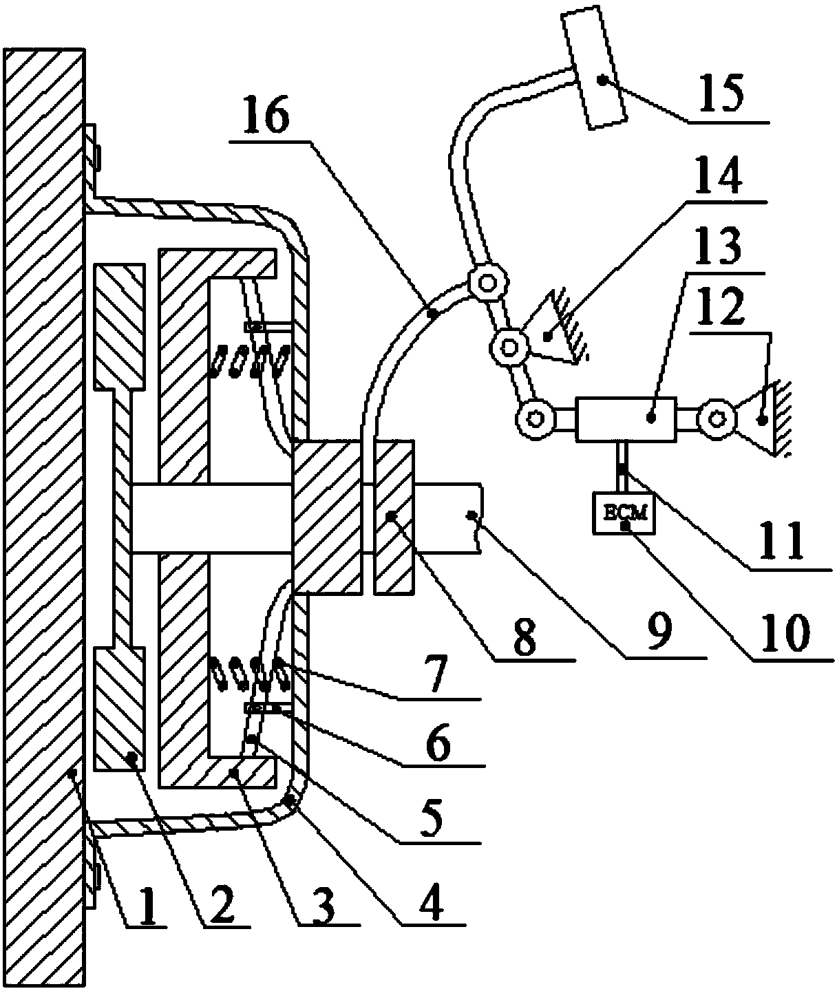
[0023] see figure 1 . The clutch cover 4 is fixed on the flywheel 1 of the engine. One end of the diaphragm spring 5 is fixed to the clutch pressure plate 3, the other end of the diaphragm spring 5 is in contact with the release bearing 8, and the middle part of the diaphragm spring 5 is fixed to the clutch cover 4 by the diaphragm spring support 6 and forms a lever. The two ends of the return spring 7 are fixed on the driven disc 2 and the clutch cover 4 respectively. The driven disk 2 is fixed to the output shaft 9. The pressure plate 3 and the release bearing 8 can slide axially on the output shaft 9 .

[0024] Clutch pedal 15 is connected with pedal lever, and pedal lever is hinged with pedal lever fixed support 14, and forms a lever mechanism, and its first lever arm is hinged with separation fork 16, and the second lever arm is hinged with one end of cont...


PUM


Abstract

The invention discloses a control mechanism for a clutch. The control mechanism comprises a clutch pedal and a pedal rod connected with the clutch pedal. The pedal rod is hinged to a pedal rod fixing support. A lever mechanism is formed, a first lever arm of the lever mechanism is hinged to a separation shifting fork, a second lever arm of the lever mechanism is hinged to one end of a controllable variable damper, and the other end of the controllable variable damper is hinged to a damper fixing support. The controllable variable damper is controlled by an electronic control module. According to the control mechanism for the clutch, an original structure of the clutch is not greatly changed, the design cost and the improvement cost are saved, the control requirement of a driver for the clutch is reduced, and the operation strength of the driver is reduced. When an existing clutch is designed, a free stroke is reserved, and the driver does not easily control the clutch due to the existence of the free stroke. However, the control process of actively controlling the control mechanism is not affected by the free stroke of the pedal.

Description

technical field [0001] The invention relates to an operating mechanism of a friction disc clutch for a vehicle. Background technique [0002] Now there are power transmission systems in the form of hydraulic torque converter, stepless chain transmission and stepless belt transmission, but mechanical power transmission system is still widely used in vehicles due to its advantages of large transmission torque, high transmission efficiency and good reliability. widely used. [0003] The clutch is one of the important mechanical parts of the vehicle's mechanical power transmission system. It is located between the engine and the gearbox and mainly undertakes the functions of power transmission and cut-off. When the vehicle is running normally, the clutch is engaged and plays the role of power transmission. When the vehicle needs to shift gears, it is necessary to cut off the power between the engine and the gearbox, and the clutch is in a disengaged state. [0004] The separa...

Claims


Application Information

Patent Timeline
Patent Type & Authority Applications(China)
IPC IPC(8): F16D48/06F16D23/12
Inventor 田维潘锁柱彭义增任川江邓猛
Owner XIHUA UNIV
Why Eureka
Try Eureka