Structure of furnace body of cracking furnace

A furnace structure and cracking furnace technology, which are applied in cracking, non-catalytic thermal cracking, petroleum industry, etc., can solve the problem of uneven thermal field distribution of flue gas flow field in the furnace, improve thermal field distribution, increase operation cycle, The effect of uniform heat distribution

Active Publication Date: 2014-08-06
CHINA PETROCHEMICAL CORP +1
View PDF2 Cites 0 Cited by
  • Summary
  • Abstract
  • Description
  • Claims
  • Application Information

AI Technical Summary

Problems solved by technology

[0004] In order to solve the problem of uneven distribution of the flue gas flow field and heat field in the furnace in the prior art, the present invention provides a cracking furnace body structure

Method used


Image

  • Structure of furnace body of cracking furnace
  • Structure of furnace body of cracking furnace

Examples


Embodiment 1

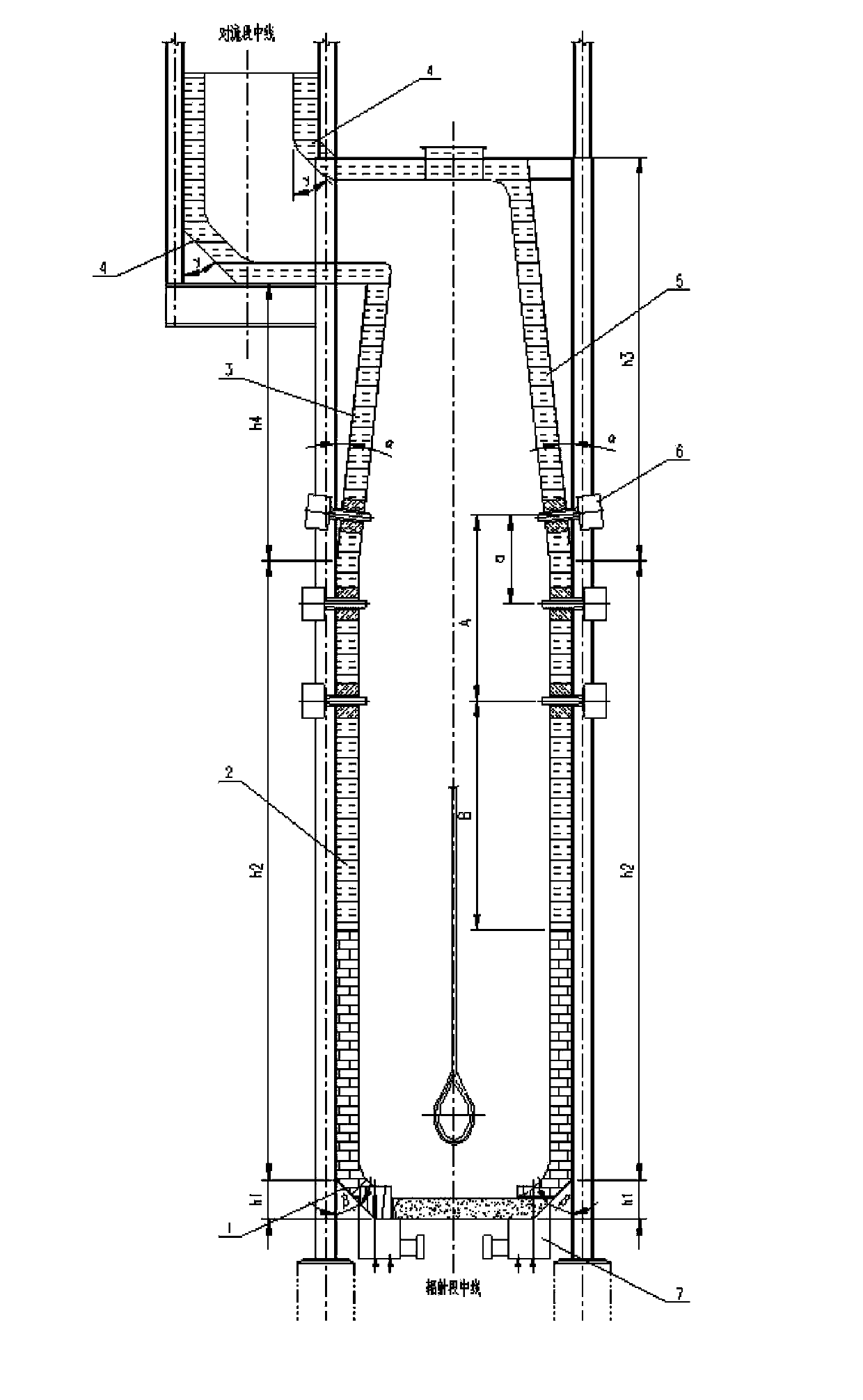
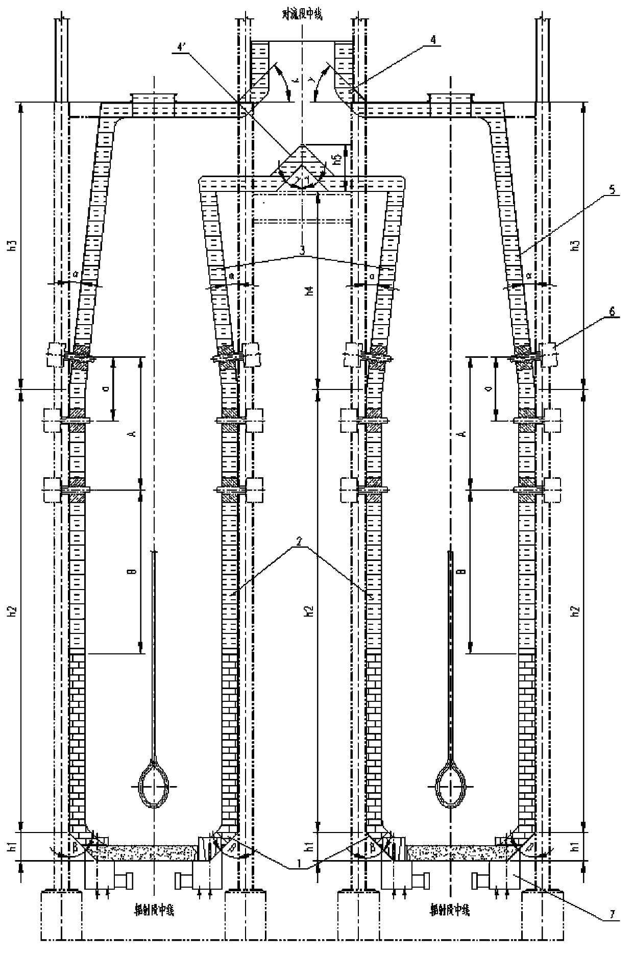
[0034] ⑴. For a single-hearth box-type cracking furnace: such as figure 1 As shown, the radiant chamber is composed of a furnace, one side wall is high and the other is low. The walls on both sides are composed of constriction structure, straight wall and slope transition structure from top to bottom, and the transition section is composed of slope transition structure. The angle between the inclined wall and the center line of the radiation section is α, the angle between the furnace bottom transition slope and the center line of the radiation section is β, and the angle range is 0°<α≤20°, 0°<β≤45°; the slope of the transition section The included angle with the centerline of the radiant section is γ, and the angle range of the included angle γ is 0°<γ≤45° to ensure the flue gas flow pattern of the radiant furnace. At the bottom of the radiant furnace, the distance between the burner and the furnace center line is L, the distance between the side wall burners is a, the number...


PUM


Abstract

The invention provides a structure of a furnace body of a cracking furnace. The structure includes a convection section, a radiation section and burners, wherein the convection section and the radiant section are connected with each other through a transition section; the furnace body comprises a flue gas overflowing area change section which is arranged near an outlet of the upper end of a radiation chamber, and the overflowing quantity is allowed to be changed before flue gas after combustion goes into the convection section; the flue gas overflowing area change section is arranged at the lower edge of the outlet of the radiation chamber, and the flue gas overflowing area change section is of a necking-down structure. The above structure can effectively solve the problems that the eddy current and the bias current of the transition section in a radiation hearth are relatively large, improve the heat field distribution in the radiation hearth and increase the operating cycle.

Description

technical field [0001] The invention relates to the field of petrochemical equipment, and furthermore, relates to a cracking furnace body structure used for ethylene industrial cracking furnaces. Background technique [0002] Ethylene cracking furnaces in industrial furnaces can usually be divided into double-hearth cracking furnaces and single-hearth cracking furnaces according to the furnace type. However, both single-hearth and double-hearth cracking furnaces have uneven heat distribution in the radiation chamber due to the furnace body configuration. The flue gas eddy current and bias flow phenomenon in the transition section affect the distribution of the thermal field in the furnace as a whole, thereby affecting the operation cycle. The specific reasons are as follows: 1. The walls of the furnace body are both vertical and horizontal walls, and the connection between the horizontal and vertical walls is also a right-angle connection, which makes the eddy current and bi...

Claims


Application Information

Patent Timeline
IPC IPC(8): C10G9/18
Inventor 孙向军薛磊李光郭玉萍刘克刚刘敬坤李森胡鸣袁慕军门宽亮高景芬张艳
Owner CHINA PETROCHEMICAL CORP
Why Eureka
Try Eureka