
Clamping mechanism for automatic pipe cutter

The technology of a clamping mechanism and a pipe cutting machine, which is applied in the field of machinery, can solve the problems that pipes cannot be well fixed, the pipe cutting machine is bulky, and the flatness of the incision is poor, and achieves the effects of compact structure, low price, and reliable fixing.

Inactive Publication Date: 2014-08-06
SUZHOU GENFU MACHINERY SCI & TECH
View PDF7 Cites 5 Cited by
  • Summary
  • Abstract
  • Description
  • Claims
  • Application Information

AI Technical Summary

Problems solved by technology

[0002] Pipe cutting machine is the most commonly used machine in the processing of pipe products. It is usually divided into two types: sawing type and ring cutting type. When sawing, the pipe cutting machine has a simple structure, but the cut is poor in flatness and cannot adapt to larger sizes. The circular cutting pipe cutting machine has good adaptability and neat incision, but the mechanism is complicated and the cost is high. The pipe cutting machine made for cutting large pipes is bulky, but the adaptability is poor, and it cannot be fixed well for pipes of different sizes. , and usually use pneumatic or hydraulic equipment to realize the operation of the clamping mechanism, there are many equipments, and it is inconvenient to use

Method used


Image

  • Clamping mechanism for automatic pipe cutter

Examples


Embodiment Construction

[0012] The following will clearly and completely describe the technical solutions in the embodiments of the present invention. Obviously, the described embodiments are only some of the embodiments of the present invention, rather than all the embodiments. Based on the embodiments of the present invention, all other embodiments obtained by persons of ordinary skill in the art without making creative efforts belong to the protection scope of the present invention.

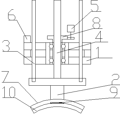
[0013] see figure 1 , the embodiment of the present invention includes:

[0014] A clamping mechanism for an automatic pipe cutting machine, comprising: a bracket 1, a push rod 2, a polished rod 3, a lead screw 4, a motor 5, a controller 6, a locking seat 7, a drive sleeve 8 and a sensor 9, and a bracket 1 A motor 5 is arranged on the top, the front end of the motor 5 is connected with a drive sleeve 8, the push rod 2 is connected with a lead screw 4 and a polished rod 3, the lead screw 4 and the polished rod 3 are ...


PUM


Abstract

The invention discloses a clamping mechanism for an automatic pipe cutter. The clamping mechanism comprises a support, a push rod, polish rods, a screw rod, a motor, a controller, a locking seat, a drive sleeve and a sensor. The motor is arranged on the support, the front end of the motor is connected with the drive sleeve, the push rod is connected with the screw rod and the polish rods, the screw rod and the polish rods are connected with the support, the screw rod is sleeved with the drive sleeve, the front end of the push rod is connected with the locking seat and the sensor, and the controller is arranged on the support. The clamping mechanism for the automatic pipe cutter has the advantages of being high in reliability, precise in locating, compact in structure, high in transfer speed, firm in fixing, low in cost, safe and clean and capable of effectively locking tubular objects.

Description

technical field [0001] The invention relates to the mechanical field, in particular to a clamping mechanism for an automatic pipe cutter. Background technique [0002] Pipe cutting machine is the most commonly used machine in the processing of pipe products. It is usually divided into two types: sawing type and ring cutting type. When sawing, the pipe cutting machine has a simple structure, but the flatness of the cut is poor, and it cannot adapt to larger sizes. The circular cutting pipe cutting machine has good adaptability and neat incision, but the mechanism is complicated and the cost is high. The pipe cutting machine made for cutting large pipes is bulky, but the adaptability is poor, and it cannot be fixed well for pipes of different sizes. , and usually use pneumatic or hydraulic equipment to realize the operation of the clamping mechanism. There are many equipments and it is inconvenient to use. Contents of the invention [0003] The technical problem mainly solv...

Claims


Application Information

Patent Timeline
Patent Type & Authority Applications(China)
IPC IPC(8): B26D7/02
Inventor 朱宝华
Owner SUZHOU GENFU MACHINERY SCI & TECH
Learn More